Multiple-spark ignition system for internal combustion engine

a multi-spark ignition and internal combustion engine technology, applied in the direction of electric ignition installation, machines/engines, mechanical equipment, etc., can solve the problems of worse fuel ignition performance, and achieve good fuel ignition performance

Active Publication Date: 2007-08-02
DENSO CORP
View PDF8 Cites 36 Cited by
  • Summary
  • Abstract
  • Description
  • Claims
  • Application Information

AI Technical Summary

Benefits of technology

[0007]Therefore, an object of the invention is to provide an improved ignition system that can give a good fuel ignition performance even if the battery voltage fluctuate.

Problems solved by technology

If the charging time increases, a ignition-less period in which the ignition spark is not generated increases, resulting in that the fuel ignition performance gets worse.

Method used


Image

  • Multiple-spark ignition system for internal combustion engine
  • Multiple-spark ignition system for internal combustion engine
  • Multiple-spark ignition system for internal combustion engine

Examples


first embodiment

[0030]An ignition system according to the invention will be described with reference to FIGS. 1-6A and 6B.

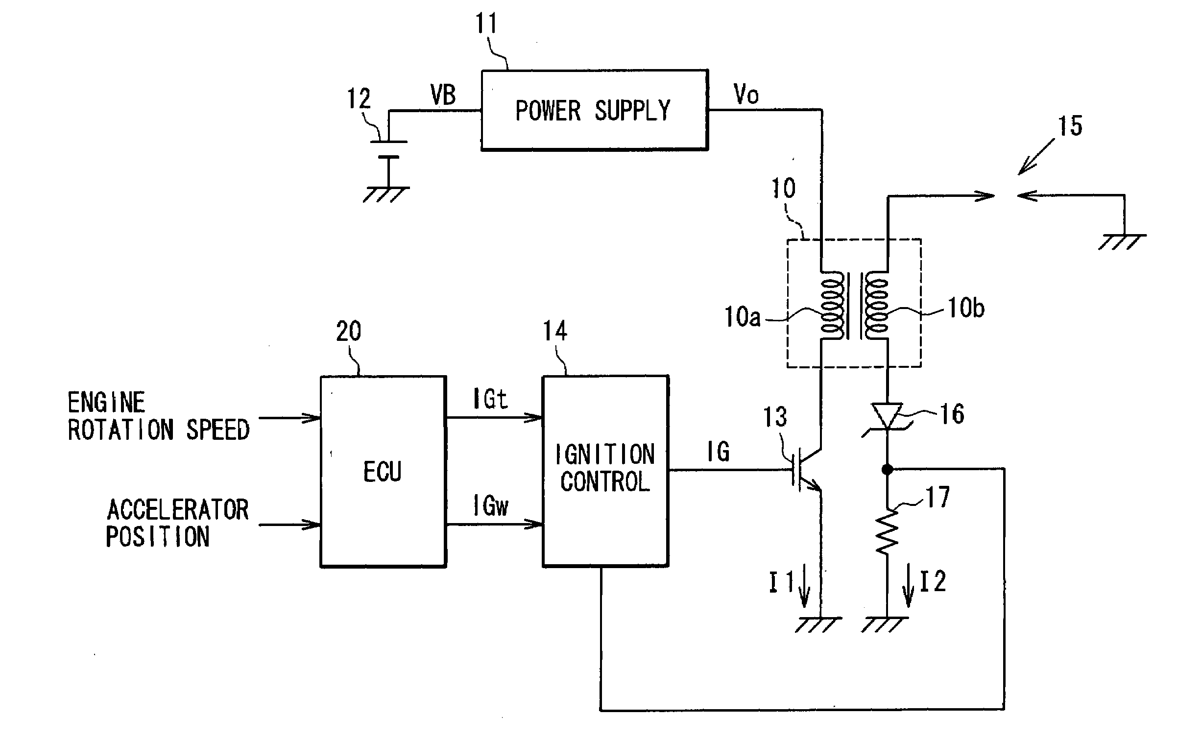
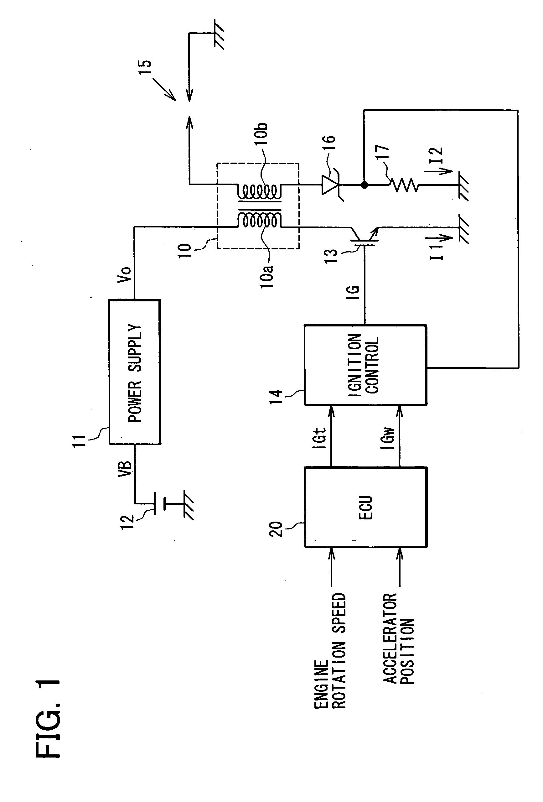
[0031]As shown in FIG. 1, the ignition system includes an ignition coil 10, a power supply circuit 11, a battery 12, an insulated gate bipolar transistor (hereinafter referred to as the IGBT) 13, an ignition control circuit 14, a spark plug 15, a zener diode 16, a current measuring resistor 17, an ECU 20, etc.

[0032]The ignition coil 10 has a primary coil 10a and a secondary coil 10b. The primary coil 10a has a pair of ends, one of which connected via the power supply circuit 11 to a high side (e.g. 12 V) terminal of the battery 12 and the other of which is connected to a ground via the IGBT 13.

[0033]The IGBT 13 has a gate connected to the ignition control circuit 14, which controls the switching operation of the IGBT 13. The power supply circuit 11 is constituted of a common boosting DC-DC converter that includes an inductor, a switching element and a capacitor to provide a volt...

second embodiment

[0045]An ignition system according to the invention will be described with reference to FIGS. 7 and 8.

[0046]Incidentally, the same reference numeral as the first embodiment represents the same or substantially the same portion, part or component as the first embodiment, hereafter.

[0047]As shown in FIG. 7, the ignition system includes a capacitor-discharge circuit (hereinafter referred to as the CD circuit) 30 in addition to the ignition coil 10, power supply circuit 11, battery 12, the IGBT 13, the ignition control circuit 14, the spark plug 15, the current measuring resistor 17 and the an ECU 20. The zener diode 16 that is connected in series with the current measuring resistor 17 is replaced by a backflow prevention diode 35 that is connected in series with the primary coil 10 and the IGBT 13. It may be considered that the CD circuit 30 is included in the power supply circuit 11.

[0048]The CD circuit 30 includes a series circuit of an energy accumulation coil 31 and a second IGBT 3...


PUM


Abstract

An ignition system for an internal combustion engine includes an ignition coil, electric power supply circuit, a switching transistor, engine condition detecting element or unit that detects a signal relating to flow speed of air-fuel-mixture gas in the engine, and ignition control unit that controls the switching transistor to provide multiple ignition sparks in a predetermined ignition period. The ignition control unit controls the switching transistor to maintain each of the ignition sparks according to the signal relating to the flow speed of air-fuel-mixture gas in the engine to maintain sufficient spark energy for igniting the air-fuel mixture gas.

Description

CROSS REFERENCE TO RELATED APPLICATION[0001]The present application is based on and claims priority from Japanese Patent Applications 2006-21962, filed Jan. 31, 2006, and 2006-198667, filed Jul. 20, 2006, the contents of which are incorporated herein by reference.BACKGROUND OF THE INVENTION[0002]1. Field of the Invention[0003]The present invention relates to an ignition system for an internal combustion engine, and particularly to a multiple-spark ignition system for igniting the fuel in the engine by multiple electric ignition sparks each ignition timing.[0004]2. Description of the Related Art[0005]P2003-521619A (WO01 / 055588) discloses a multiple-spark ignition system, in which a switching means is turned on or off according to the amount of the primary current flowing from a battery through the primary coil and the amount of the secondary current (discharging current) flowing through the secondary coil of an ignition coil. In more detail, the switching means turns off to generate ...

Claims


Application Information

Patent Timeline
Patent Type & Authority Applications(United States)
IPC IPC(8): F02P15/08F02P3/05F02P3/04
CPCF02P3/051Y02T10/46F02P15/08F02P5/1502F02P9/007Y02T10/40
Inventor WADA, JYUNICHIYOSHINAGA, TORU
Owner DENSO CORP
Why Eureka
Try Eureka