Saddle-straddling type motor vehicle

a motor vehicle and saddle technology, applied in the direction of machines/engines, cycles, cycle equipment, etc., can solve the problems of long distance between the fuel injection device and the combustion chamber, difficulty in sufficiently cooling the fuel injection device, and vapor lock or breathing, etc., to achieve the effect of low cost and simple structur

Inactive Publication Date: 2007-08-02
YAMAHA MOTOR CO LTD
View PDF9 Cites 11 Cited by
  • Summary
  • Abstract
  • Description
  • Claims
  • Application Information

AI Technical Summary

Benefits of technology

[0071] According to the present invention, while the motor vehicle is stopped or running at low speed, the fuel injection device is cooled by air supplied to the fuel injection device from the secondary passage, and when the motor vehicle runs, the fuel injection device is cooled by the wind that hits the cylinder head. The fuel injection device is thus cooled with a simple structure and at low cost. It is thus possible to prevent formation of vapor in the fuel and to provide precise control of the fuel injection.

Problems solved by technology

This causes vapor in the fuel injected by the fuel injection device 8, causing troubles like vapor lock or breathing.
However, placing the fuel injection device 8 apart from the engine 4 lengthens the distance of fuel transport from the fuel injection device to the combustion chamber.
However, it is still difficult to sufficiently cool the fuel injection device.

Method used


Image

  • Saddle-straddling type motor vehicle
  • Saddle-straddling type motor vehicle
  • Saddle-straddling type motor vehicle

Examples


first embodiment

(1) FIRST EMBODIMENT

[0088] (a) Entire Structure of Motorcycle

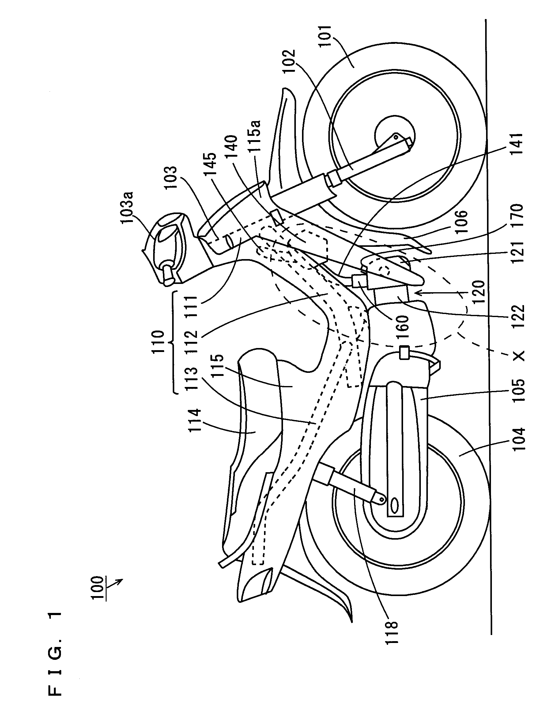
[0089]FIG. 1 is a side view of a motorcycle according to a first embodiment of the present invention. It should be noted that, in the description below, the front, rear, left, and right indicate the directions seen from a rider seated on the seat of the motorcycle.

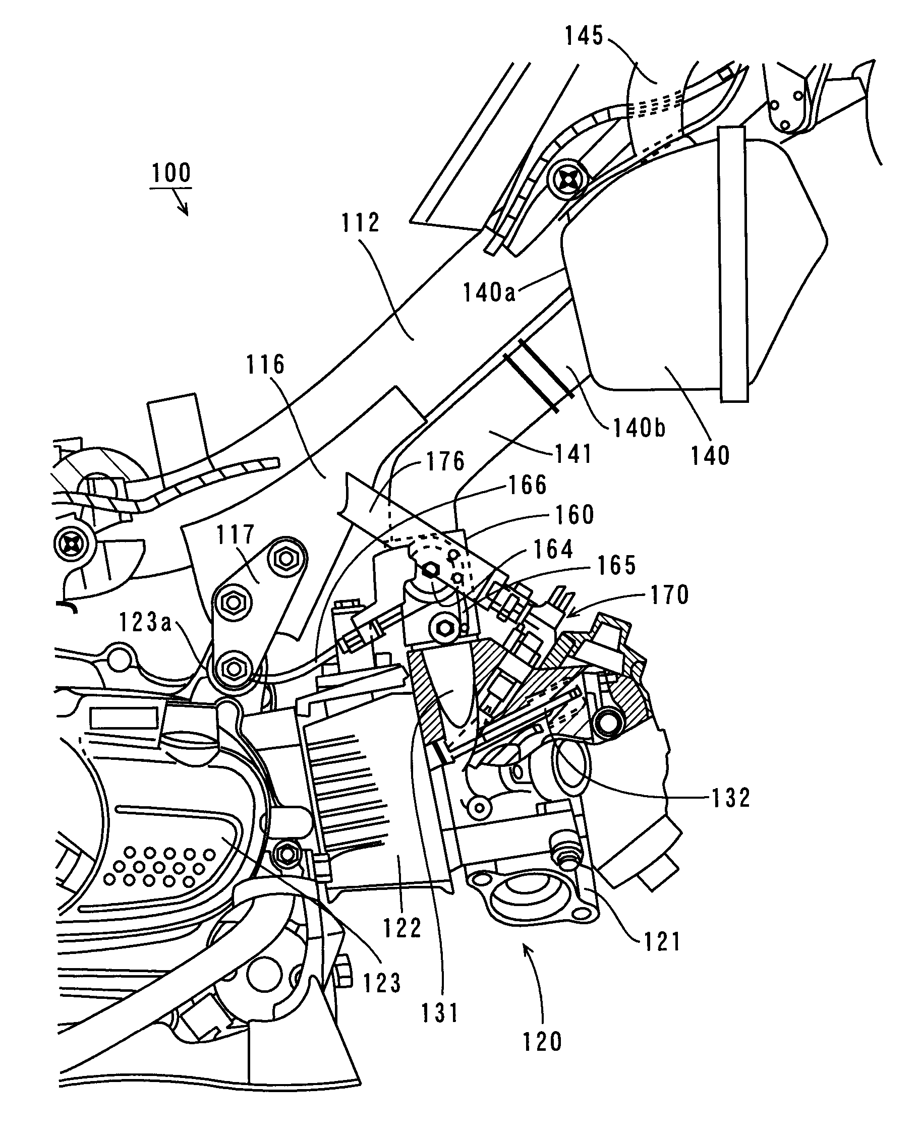
[0090] The motorcycle 100 shown inFIG. 1 has an under-bone type body frame (hereinafter referred to simply as a body frame) 110. An air-cooled engine 120 is hung and fixed under a front part of the body frame 110. The body frame 110 is formed of a head pipe 111, a backbone 112, and a seat rail 113.

[0091] A steering shaft 103 is attached to the head pipe 111 so that the steering shaft 103 can be turned to the right and left. Handles 103a are attached at the top end of the steering shaft 103. A front fork 102 is connected to the steering shaft 103 to rotatably support a front wheel 101. A fender 106 is attached to cover the front wheel 101 above and behind the f...

second embodiment

(2) SECOND EMBODIMENT

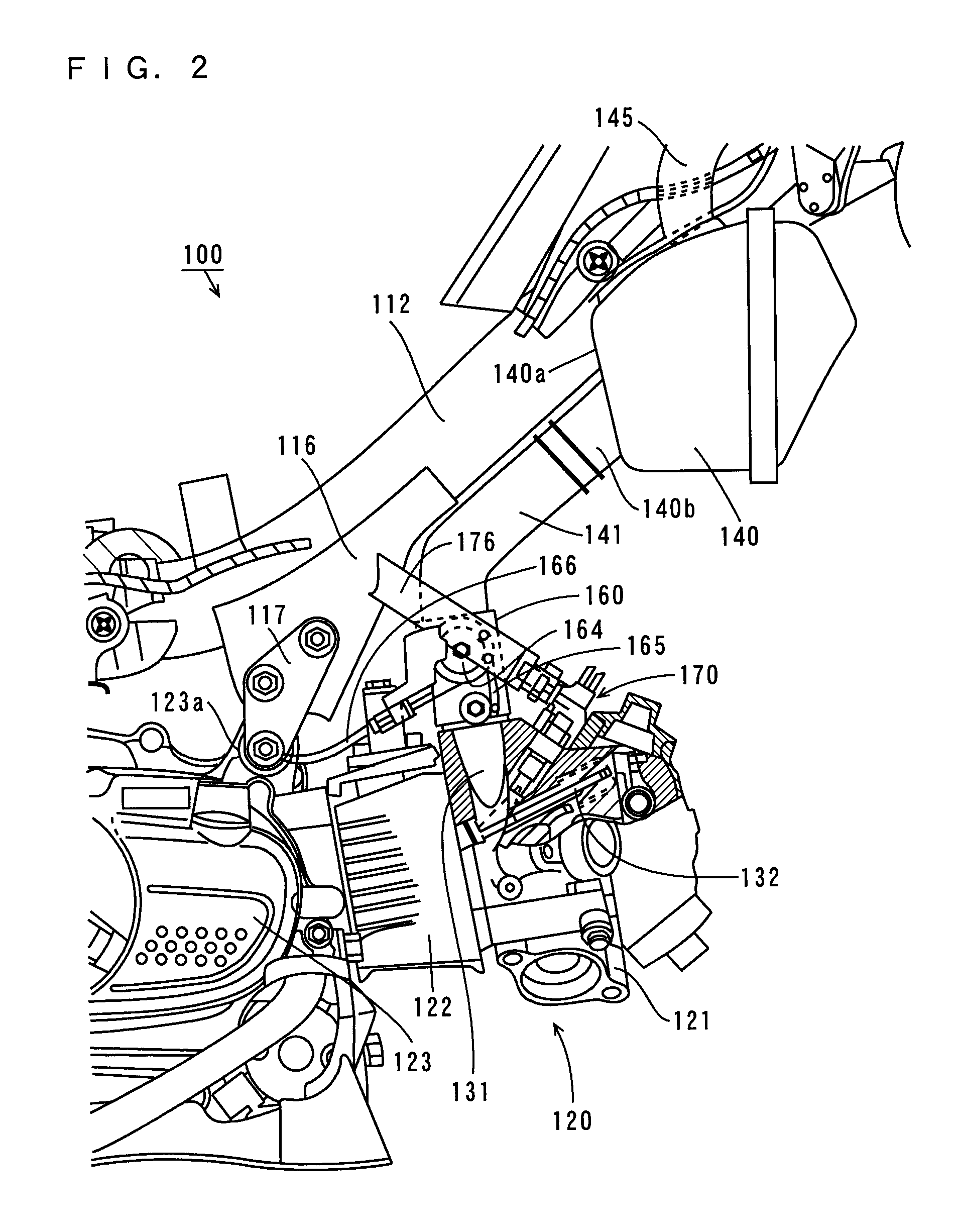
[0195]FIG. 11 is an enlarged partially cross-sectional view showing the engine of a motorcycle according to a second embodiment of the present invention. FIG. 12 is a diagram showing the structure of a main part of the engine of FIG. 11 seen from the front.

[0196] The motorcycle 200 of the embodiment has the same basic structure as the motorcycle 100 of the first embodiment except in the following respects. In FIGS. 11 and 12, the same components as those depicted in FIGS. 1 and 2 are shown at the same reference numerals.

[0197] As shown in FIGS. 11 and 12, the motorcycle 200 of the second embodiment differs from the motorcycle 100 of the first embodiment in the positioning of a fuel injection device 270 and in that a single exhaust valve opening 127 and a single intake valve opening 128 are provided.

[0198] In the motorcycle 200 of the second embodiment, as in the motorcycle 100 of the first embodiment, an air-cooled engine 220 is hung and fixed under a backbon...


PUM


Abstract

An air-cooled engine is hung and fixed under a rear part of a backbone of a body frame. The engine is disposed so that the center axis of a cylinder in its cylinder block extends approximately horizontally and so that its cylinder head is directed toward the front. A fuel injection device is located between an intake valve and an intake port in the cylinder head. An injection nozzle of the fuel injection device and an intake valve opening are placed at a short distance. While the vehicle is idling or running at low speed, the vicinity of the tip of an injector of the fuel injection device is cooled by assist air supplied from a throttle body through a secondary passage, and when the vehicle runs normally or at high speed, the fuel injection device is cooled by the wind that hits the cylinder head.

Description

TECHNICAL FIELD [0001] The present invention relates to a saddle-straddling type motor vehicle, such as a two-wheeled or three-wheeled motorcycle, equipped with an engine having a fuel injection device. BACKGROUND ART [0002] Some conventionally known motor vehicles designed to be straddled by riders, such as under-bone type two-wheeled and three-wheeled motorcycles, have electronically-controlled fuel injection devices in place of carburetors in the intake systems of engines. For example, the under-bone type motorcycles described in Patent Documents 1 and 2 have engines attached under the backbones. In the motorcycles, a fuel injection device is positioned downstream of a throttle valve, in an intake passage that communicates to an intake valve opening of the engine. [0003]FIG. 14 is apartial side view showing an example of a conventional under-bone type motorcycle equipped with an engine having a fuel injection device (see Patent Document 1). FIG. 14 shows the intake system partial...

Claims


Application Information

Patent Timeline
Patent Type & Authority Applications(United States)
IPC IPC(8): B62K11/00F02M51/00F02B23/00B62J99/00F02B61/02F02B75/00F02M53/08F02M69/00F02M69/04F02M69/08
CPCB62K2202/00F02B61/02F02B75/005Y02T10/123F02M53/08F02M69/044F02M69/047F02B2275/16Y02T10/12
Inventor ISHII, WATARUTSUZUKU, HIROYUKIHANAJIMA, TOSHIHARU
Owner YAMAHA MOTOR CO LTD
Why Eureka
Try Eureka