Optical transmitter apparatus

Inactive Publication Date: 2007-08-02
FUJITSU LTD
View PDF6 Cites 90 Cited by
  • Summary
  • Abstract
  • Description
  • Claims
  • Application Information

AI Technical Summary

Benefits of technology

[0019] The phase (and intensity) of the first and second modulation signals depends on the first and second DC bias provided to the first and second phase modulation elements. The power of the AC component of the optical signal output from the intensity modulator becomes minimum when the first bias and the second bias are optimized. Therefore, a phase-modulated signal with an appropriate phase corresponding to the first and second driving signals can be generated by adjusting the first bia

Problems solved by technology

However, the DQPSK is a technology under development, and still has a number of problem

Method used


Image

  • Optical transmitter apparatus
  • Optical transmitter apparatus
  • Optical transmitter apparatus

Examples


Example

First Embodiment

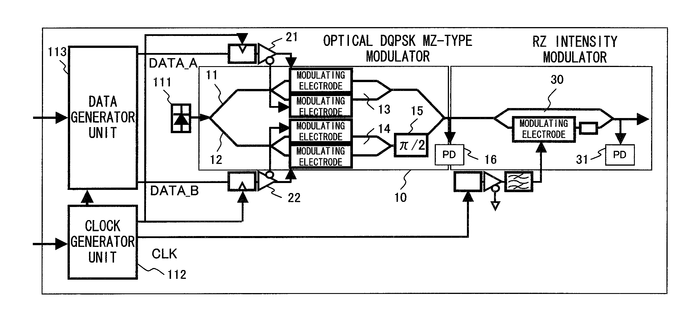
[0051]FIG. 5 is a diagram describing the configuration of an optical DQPSK transmitter apparatus of the first embodiment. The optical DQPSK transmitter apparatus of the first embodiment provides a function for adjusting the amplitude of a driving signal based on the power of the optical RZ-DQPSK signal generated by the RZ intensity modulator 30. In FIG. 5, descriptions of the clock generator unit 112 and the data generator unit 113 are omitted.

[0052] The photodetector 31 converts the optical RZ-DQPSK signal output from the RZ intensity modulator 30 into an electrical signal (hereinafter referred to as a “monitor signal”). A capacitor C removes a DC component from the monitor signal obtained by the photodetector 31. By so doing, an AC component of the optical RZ-DQPSK signal is extracted. An amplifier 41 amplifies the monitor signal from which the DC component is removed. A power detector unit 42 detects power of the monitor signal amplified by the amplifier 41. The...

Example

Second Embodiment

[0066]FIG. 9 is a diagram describing the configuration of the optical DQPSK transmitter apparatus of the second embodiment. The optical DQPSK transmitter apparatus of the second embodiment provides a function for adjusting the DC bias of each of the phase modulators 13 and 14 in the optical DQPSK modulator 10, based on the power of the optical RZ-DQPSK signal generated by the RZ intensity modulator 30. Note that the descriptions of the clock generator unit 112 and the data generator unit 113 are omitted.

[0067] In FIG. 9, the monitor unit (i.e. the photodetector 31, the capacitor C, the amplifier 41 and the power detector 42) is basically the same as that of the first embodiment. In other words, the monitor unit detects the power of the optical RZ-DQPSK signal and generates a monitor signal.

[0068] A minimum power detector unit 51 and a bias adjuster unit 52 adjust the DC bias for adjusting the operation point of the phase modulators 13 and 14 so that the power of ...

Example

Third Embodiment

[0077]FIG. 14 is a diagram describing the configuration of the optical DQPSK transmitter apparatus of the third embodiment. The optical DQPSK transmitter apparatus of the third embodiment comprises a function for adjusting the amount of phase shift of the phase shifter 15 of the optical DQPSK modulator 10 in addition to the DC bias control function of the second embodiment.

[0078] A control unit 60 provides the DC bias control function and the phase shift amount adjusting function based on the power of the monitor signal obtained by the power detector unit 42. Here, the control unit 60 is realized by a CPU, for example, executing a prepared program. A gain adjuster unit 61 is the same as the minimum power detector unit 51 and the bias adjuster unit 52 shown in FIG. 9.

[0079] The amount of phase shift of the phase shifter 15 has to be accurately adjusted at π / 2, as stated above. The amount of phase shift of the phase shifter 15, particularly in this embodiment, is ad...


PUM


Abstract

An optical DQPSK modulator comprises a pair of phase modulators. Each of the pair of the phase modulators is provided with first and second driving signals. The first and second driving signals are amplified by first and second amplifiers, respectively. An RZ intensity modulator generates an optical RZ-DQPSK signal from an optical DQPSK signal output from the optical DQPSK modulator. A photodetector generates a monitor signal from the optical RZ-DQPSK signal. A gain adjuster unit adjusts the gains of the first and second amplifiers so as to minimize the power of the monitor signal.

Description

BACKGROUND OF THE INVENTION [0001] 1. Field of the Invention [0002] The present invention relates to an optical transmitter apparatus for generating and transmitting a phase-modulated optical signal, and particularly relates to an optical transmitter apparatus for generating and transmitting an optical DQPSK signal. [0003] 2. Description of the Related Art [0004] Phase modulation has been in practical use as one of the technologies for transmitting signals in an optical transmission system. In the phase modulation, data is transmitted by controlling the phase of a carrier wave in accordance with the transmission data. For example, in QPSK (Quadrature Phase Shift Keying) modulation, “θ”, “θ+π / 2”, “θ+π”, and “θ+3π / 2” are assigned respectively to each symbol “00”, “10”, “11”, and “01”, consisting of two bit data. Here, the “θ” is an arbitrary phase. A receiver device recovers the transmission data by detecting the phase of the received signal. [0005] DQPSK (Differential Quadrature Phas...

Claims


Application Information

Patent Timeline
IPC IPC(8): H04B10/12G02F1/01H04B10/516H04B10/07H04B10/2507H04B10/54H04B10/556H04B10/564H04B10/61
CPCG02F1/2255H04B10/505H04B10/5051H04B10/5053H04B10/5561H04B10/50575H04B10/50577H04B10/5162H04B10/50572
Inventor AKIYAMA, YUICHI
Owner FUJITSU LTD
Why Eureka
Try Eureka