Scroll compressor

a compressor and roller technology, applied in the direction of machines/engines, rotary/oscillating piston pump components, liquid fuel engines, etc., can solve the problems of uneven contact pressure between the teeth tips of the fixed scroll part and the teeth bottoms of the orbiting scroll part, deterioration of durability, and generation of so as to prevent galling or abnormal wear

Inactive Publication Date: 2007-08-02
PANASONIC CORP
View PDF2 Cites 41 Cited by
  • Summary
  • Abstract
  • Description
  • Claims
  • Application Information

AI Technical Summary

Benefits of technology

[0067] With this aspect, even if the refrigerant is carbon dioxide and the teeth bottoms of the orbiting

Problems solved by technology

However, in the above structures, deformations of the fixed scroll part and orbiting scroll part caused by pressure are not taken into consideration, and when the scroll compressor is operated under high load or carbon dioxide is used as a refrigerant, the contact pressure acting on the teeth tips of the fixed scroll part and teeth bottoms of the orbiting scroll part becomes uneven, and there is a fear that galling or abnormal wearing is generated and there is a problem that the durability is deteriorated.
When carbon dioxide is used as a refrigerant, the discharge pressure of the compressor on the high pressure side is higher than that of the conventional compressor by about 7 to 10 times. Thus, if a back pressure enough to prevent the orbiting scroll part from separating from the fixed scroll part is applied, the orbiting scroll part is strongly pushed against the fixed scroll part, abnormal wearing or seizing is generated, and performance is deteriorated by input increase.
In a system having large capacity and uses much refrigerant, at the time of transient operation wherein liquid refrigerant returns abruptly, shortage of lubricant oil or temperature rise is generated on a thrust surface of the orbiting scroll part due to carbon dioxide liquid refrigerant having high cleaning ability, and there is a fear that seizing is generated from the aluminum surface.
When both the scroll parts are made of metal, i.e., iron-based materials having the same coefficient of thermal expansion, since the gravity of the orbiting scroll part becomes great, centrifugal force at the time of operation is increased and as a result, a load of the bearing member is increased, and sliding loss is also increased.
Especially when the scroll compressor is operated at high speed, since the centrifugal force is extremely increased, a main shaft and the bearing member are abruptly worn.
In order to enhance the precision of the l

Method used


Image

  • Scroll compressor
  • Scroll compressor
  • Scroll compressor

Examples


first embodiment

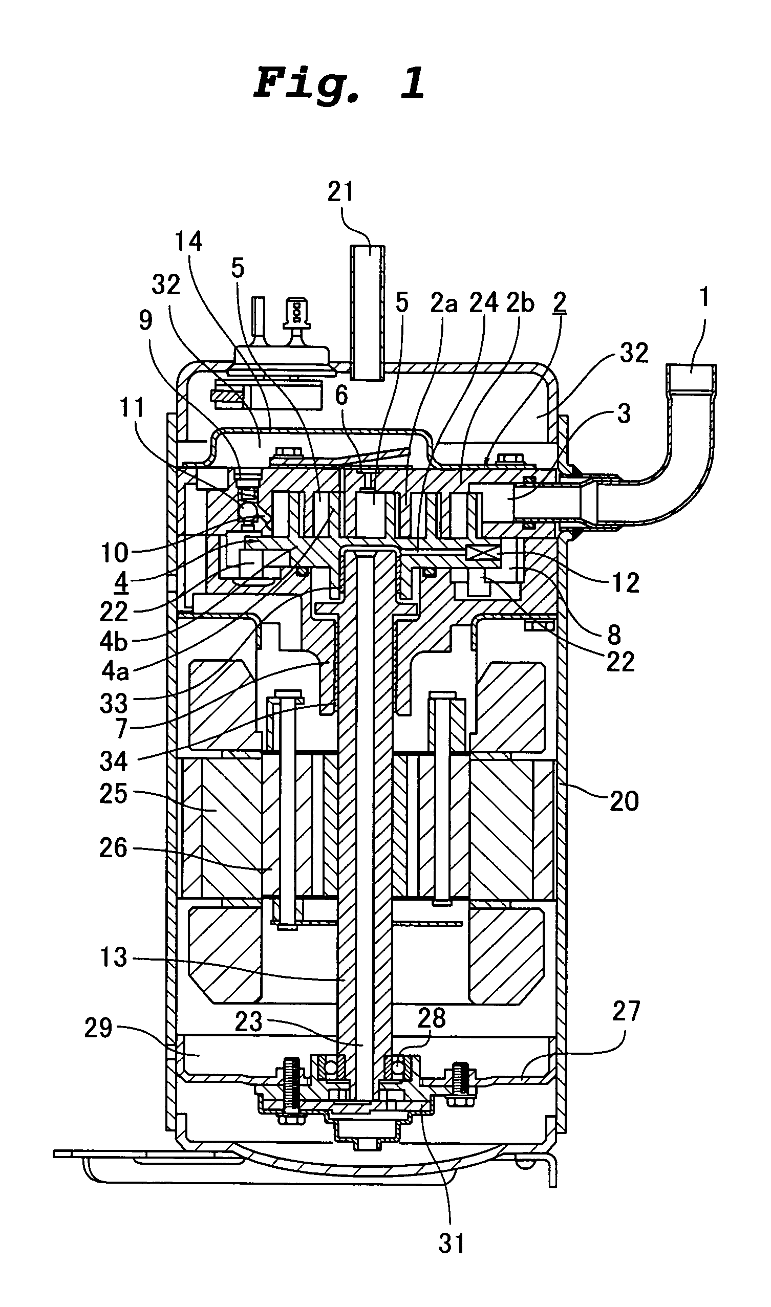
[0086]FIG. 1 is a sectional view showing a scroll compressor of a first embodiment of the present invention. In the scroll compressor of the first embodiment shown in FIG. 1, the same members as those of the conventional scroll compressor shown in FIG. 7 are designated with the same symbols.

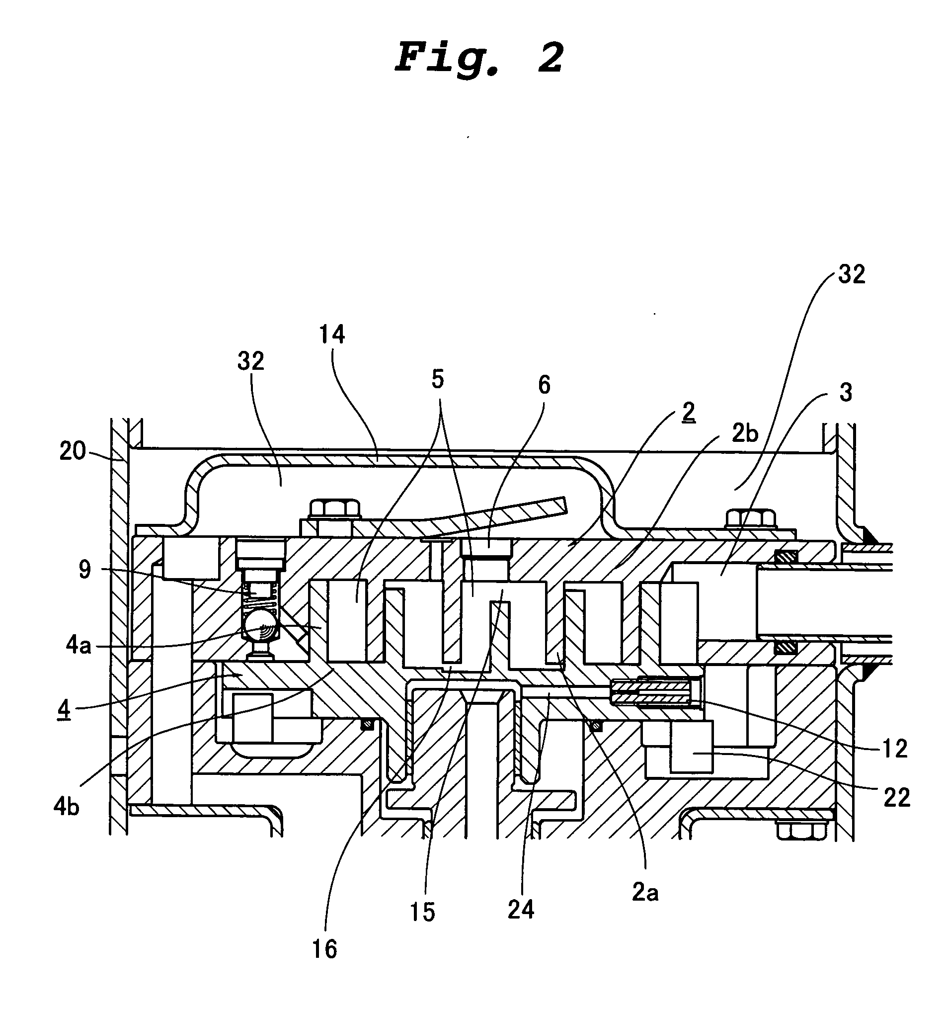
[0087] The scroll compressor of the embodiment includes a compressor mechanism and a motor mechanism in a container 20. The compressor mechanism is disposed at an upper portion in the container 20, and the motor mechanism is disposed below the compressor mechanism. The container 20 is provided at its upper portion with a suction pipe 1 and a discharge pipe 21. An oil reservoir 29 for accumulating lubricant oil is provided at a lower portion in the container 20.

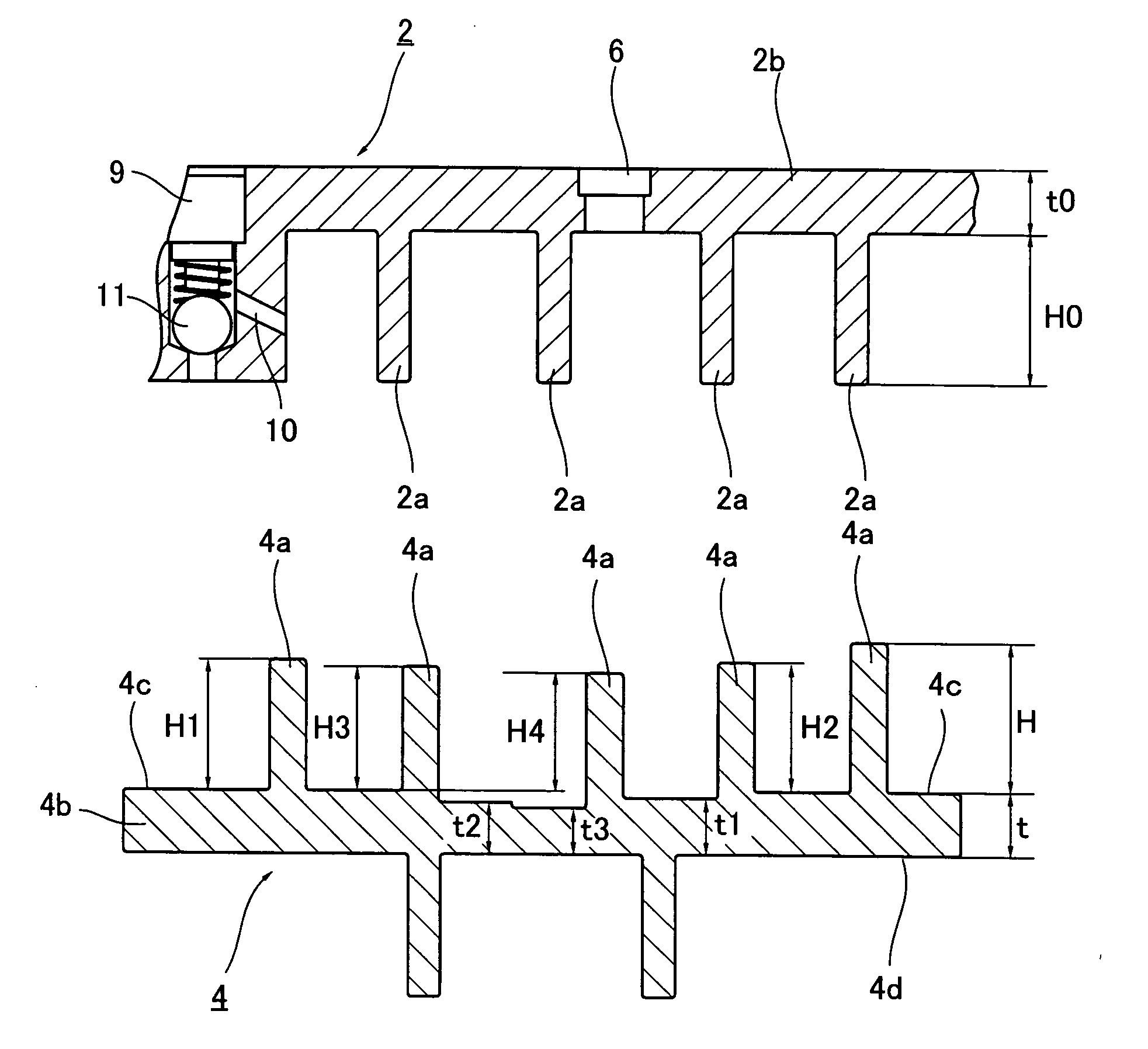
[0088] The compressor mechanism includes a fixed scroll part 2 and an orbiting scroll part 4. The fixed scroll part 2 and the orbiting scroll part 4 are meshed with each other to form a plurality of compression chambers 5. The fixed scrol...

second embodiment

[0106] Next, a scroll compressor of a second embodiment of the present invention will be explained. The scroll compressor of the second embodiment is different from that of the first embodiment in that the heights of the lap of the orbiting scroll part and the thickness of the mirror plate are set such that carbon dioxide can be used as a refrigerant, and other structure is the same as that of the first embodiment and thus, the second embodiment will be explained using the drawings of the first embodiment.

[0107] That is, when the carbon dioxide is used as the refrigerant, the operation pressure of the compressor is extremely high as compared with conventional CFCs refrigerant is used, and also at the time of steady operation, the discharge pressure rises as high as 10 MPa and the suction pressure rises as high as about 4 MPa. At that time a large pressure difference is generated between the compression chamber 5 of the mirror plate 4b of the orbiting scroll part 4 and the back pres...

third embodiment

[0114] Next, a scroll compressor of a third embodiment of the present invention will be explained. FIG. 4 is a vertical sectional view showing the scroll compressor according to the third embodiment of the invention. FIG. 5 is a sectional view of an essential portion of a compression mechanism of the scroll compressor shown in FIG. 4. FIG. 6 is a plan view of an orbiting scroll part of the scroll compressor shown in FIG. 4. FIG. 7 is a sectional view of a side surface of the orbiting scroll part of the scroll compressor shown in FIG. 4. FIG. 8 is a graph showing a height ratio of an orbiting lap of the orbiting scroll part of the scroll compressor shown in FIG. 4. In this embodiment, the same members as those of the conventional scroll compressor shown in FIG. 17 are designated with the same symbols, and the same is applied to the subsequent fourth to tenth embodiments also.

[0115] The scroll compressor of this embodiment includes a compression mechanism and a motor mechanism in a c...


PUM


Abstract

a First gap 15 in a thrust direction between teeth bottoms of a fixed mirror plate 2b and teeth tips of an orbiting lap 4a, and a second gap 16 in the thrust direction between teeth bottoms of an orbiting mirror plate 4b and teeth tips of a fixed lap 2a are formed such as to gradually increase from an outer peripheral side to an inner peripheral side of a scroll compressor, the first gap 15 is made greater than the second gap 16. Contact surface pressures of the laps 2a and 4a are kept low with respect to pressure deformation, contact pressure of the teeth tips of the fixed scroll part 2 and the teeth bottoms of the orbiting scroll part 4 are equally maintained. With this loads applied to the scroll parts 2 and 4 are equally received by a thrust surface.

Description

TECHNICAL FIELD [0001] The present invention relates to a scroll compressor in which a fixed scroll part and an orbiting scroll part are meshed with each other to form a compression chamber, the orbiting scroll part is allowed to orbit, thereby moving a compression chamber while changing its capacity to carry out suction, compression and discharge. BACKGROUND TECHNIQUE [0002] As a refrigeration air conditioning hermetic compressor, there are conventional reciprocating type, rotary type and scroll type compressors, and these compressors are used in refrigeration or air conditioning fields of domestic or business purpose. Currently, compressors are developed while utilizing characteristics in terms of costs and performance. [0003] Among them, a so-called hermetical compressor for preventing noise and eliminating the need of maintenance is a typical compressor in which a compressor mechanism and a motor are accommodated in a container, and a scroll compressor and a rotary compressor ar...

Claims


Application Information

Patent Timeline
IPC IPC(8): F01C1/02F01C1/063F03C2/00F04C18/02F04C29/02
CPCF04C18/0215F04C2230/602F04C29/028F04C18/0276F04C18/02F04C29/00
Inventor HIWATA, AKIRAFUTAGAMI, YOSHIYUKIAKAZAWA, TERUYUKIIIDA, NOBORUSAWAI, KIYOSHISHINTAKU, HIDENOBUMORIMOTO, TAKASHI
Owner PANASONIC CORP
Why Eureka
Try Eureka