Wireless Laryngoscope with Internal Antennae and One Piece Construction Adapted for Laryngoscopy Training

a laryngoscope and antenna technology, applied in the field of wireless laryngoscopes and camera systems, can solve the problems of complicated task for airway managers, bad habits, and inability to facilitate tracheal intubation with indirect laryngoscopy techniques,

Inactive Publication Date: 2007-08-02
C & V INNOVATIONS
View PDF99 Cites 67 Cited by
  • Summary
  • Abstract
  • Description
  • Claims
  • Application Information

AI Technical Summary

Benefits of technology

[0023] A further objective is to provide an electronic laryngoscope with a self-contained wireless digital camera embedded within the laryngoscope, which provides real-time indirect viewing of the field of view that is also self-contained, light weight, and portable. This image will be transmitted wirelessly to its receiver and can be viewed on any video type display.
[0024] This invention will have none of its wired predecessor's weakness and all of their strengths providing a more effective instrument for use in intubations. Not being tied do

Problems solved by technology

Richard M. Cooper, BSc MSc MD FRCPC, from the Department of Anesthesia and Pain Management, Toronto General Hospital, University of Toronto, Toronto, Ontario, Canada has eloquently introduced the need and purpose for laryngoscope noting that “man's assumption of an upright posture, coupled with our tendency to live in social groups has resulted in some bad habits—simultaneous eating and talking.
While this does make eating safer and more interesting, it has complicated the task for airway managers.”
Morell Mackenzie learned laryngoscopy from Czermak and went on to found London's first throat hospital, however, the techniques of indirect laryngoscopy were not used to facilitate tracheal intubation.
Hans Kuhn modified O'Dwyer's instruments and created a long, flexible metal endotracheal tube and introducer but the technique still depended upon blind insertion, largely because light sources were inadequate to permit progress in direct laryngoscopy.
This blade required limited mouth opening but also left little space to manipulate the endotracheal tube (ETT).
However, even “non-difficult” endotracheal intubation may be associated with airway injury.
The inability to see the larynx gene

Method used


Image

  • Wireless Laryngoscope with Internal Antennae and One Piece Construction Adapted for Laryngoscopy Training
  • Wireless Laryngoscope with Internal Antennae and One Piece Construction Adapted for Laryngoscopy Training

Examples


Embodiment Construction

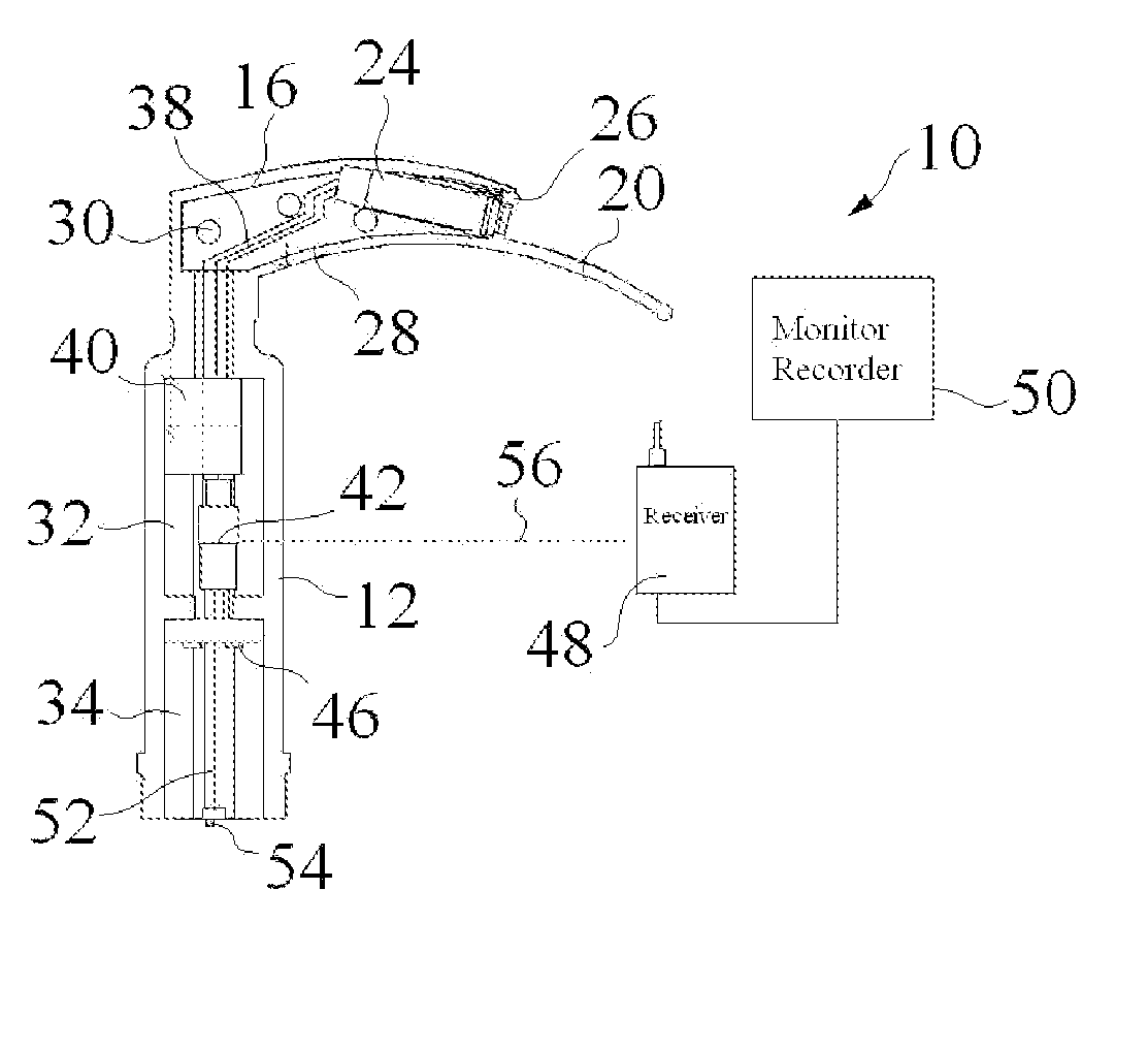
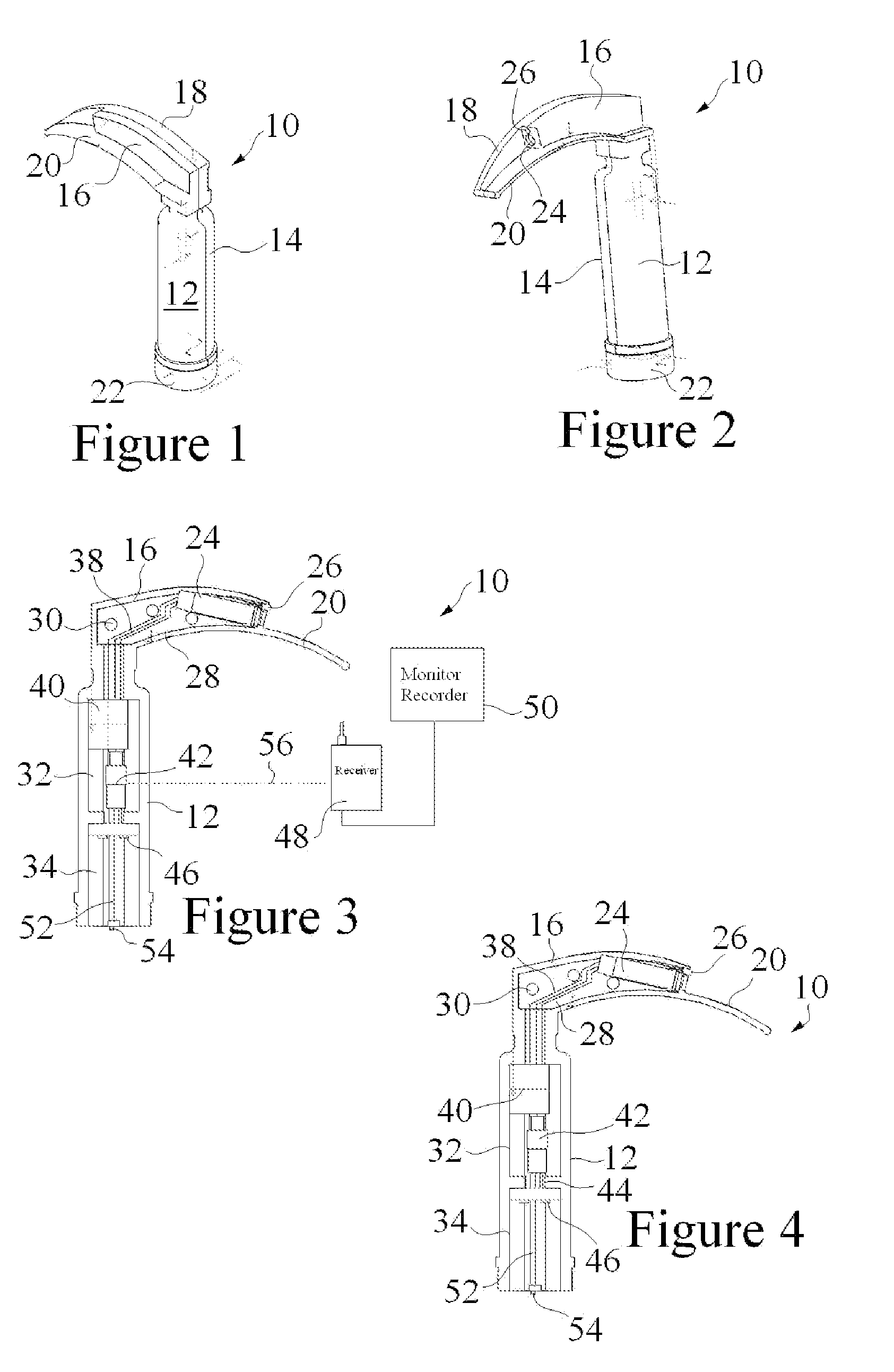
[0032]FIGS. 1 and 2 are front perspective views of a wireless laryngoscope 10 according to the present invention. The wireless laryngoscope 10 includes a front or first handle portion 12 and a second or rear handle portion 14 coupled to the first handle portion 12 and defining an internal cavity as described below. The first handle and the second handle portions 12 and 14 combine to form a handle assembly which is intended to conform to the general size and shape of conventional laryngoscope designs. The terms front and rear are merely to differentiate the handle portions 12 and 14 for purposes of explanation only. The handle portions 12 and 14 are made from any conventional material, although injection molded thermoplastic is cost effective, particularly for training purposes. In training purposes the laryngoscope 10 will likely be used on simulators (not shown) such that the laryngoscope need not be sterilized (autoclaving or the like) between uses. Consequently for constructing a...


PUM


Abstract

A wireless laryngoscope has a first and a second handle portion coupled together defining an internal cavity and combining to form a handle assembly. The laryngoscope further includes a first and a second blade portion coupled together and defining an internal cavity in at least a portion thereof and combining to form a blade assembly. A light source within the internal cavity of the blade assembly illuminates at least a portion of the blade assembly, and a camera mounted within the internal cavity of the blade assembly obtains images of the operation of the laryngoscope. A transmitter is coupled to the camera and is mounted within one internal cavity with an antenna mounted within one internal cavity coupled to the transmitter, wherein the transmitter wirelessly transmits the video images of the camera to a remote receiver.

Description

RELATED APPLICATIONS [0001] This application claims the benefit of U.S. Provisional patent application Ser. No. 60 / 758,495 filed Jan. 12, 2006 entitled “Wireless Laryngoscope.”BACKGROUND OF THE INVENTION [0002] 1. Field of the Invention [0003] The present invention relates to a wireless laryngoscope and camera system, and more particularly to a wireless laryngoscope with internal antenna and one piece construction that is particularly well suited for laryngoscopy training. [0004] 2. Background Information [0005] Dr. Richard M. Cooper, BSc MSc MD FRCPC, from the Department of Anesthesia and Pain Management, Toronto General Hospital, University of Toronto, Toronto, Ontario, Canada has eloquently introduced the need and purpose for laryngoscope noting that “man's assumption of an upright posture, coupled with our tendency to live in social groups has resulted in some bad habits—simultaneous eating and talking. This has necessitated exclusion of the larynx from the line of sight connect...

Claims


Application Information

Patent Timeline
IPC IPC(8): A61B1/267
CPCA61B1/267A61B1/0676A61B1/05A61B1/00016
Inventor MILLER, CHARLES G.KOK-YING SHA, VINCE
Owner C & V INNOVATIONS
Why Eureka
Try Eureka