Diaphragm pressure pod for medical fluids

a technology of diaphragm and pressure pod, which is applied in the direction of mechanical equipment, joints with fluid cut-off means, transportation and packaging, etc., can solve the problems of limited pressure measurement, pressure measurement error//, and use of this system

Active Publication Date: 2007-08-02
B BRAUN MEDICAL
View PDF32 Cites 77 Cited by
  • Summary
  • Abstract
  • Description
  • Claims
  • Application Information

AI Technical Summary

Problems solved by technology

As a disadvantage of these diaphragmatic systems, the great majority of over 100,000+ dialysis machines which are clinically used at the present time have their pre-pump arterial, post pump arterial and / or venous pressure ports for measuring blood pressure positioned on the face of the machine remote from other sites to which the blood tubing must be routed, such as the to the blood pump, the dialyzer (in the case of hemodialysis), the safety shut-off clamp, etc.
Thus there is a disadvantage in the use of this system.
It is a further disadvantage of the current diaphragmatic system that the non-sterile side of the diaphragm is open to atmosphere prior to being brought into sealing relation with the equipment's pressure port, and therefore may be displaced prior to use.
Such displacement results in pressure measurement errors and / or limited pressure measurements.
It is a disadvantage of sets which fit the great majority of the world's dialysis machines that they have drip chambers and permanently attached branch lines.
Such branch lines complicate the sets' construction, packaging and use and are expensive.
Where a dialyzer is remotely monitored from a machine (as is generally the case) the placing of a pressure measuring chamber or pod immediately downstream from it is impossible in the case of drip chambers or prior art pods.

Method used


Image

  • Diaphragm pressure pod for medical fluids
  • Diaphragm pressure pod for medical fluids
  • Diaphragm pressure pod for medical fluids

Examples


Embodiment Construction

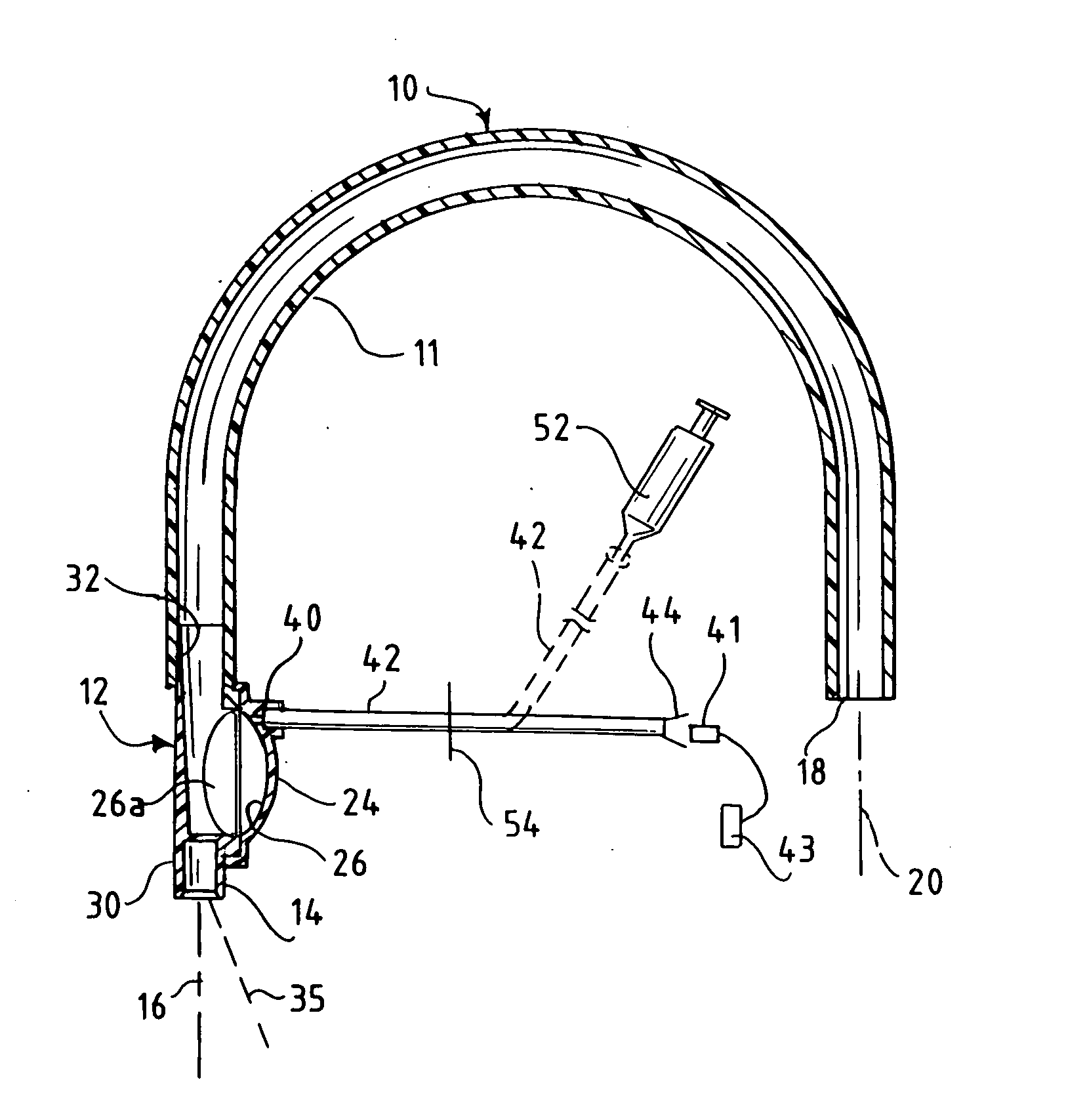
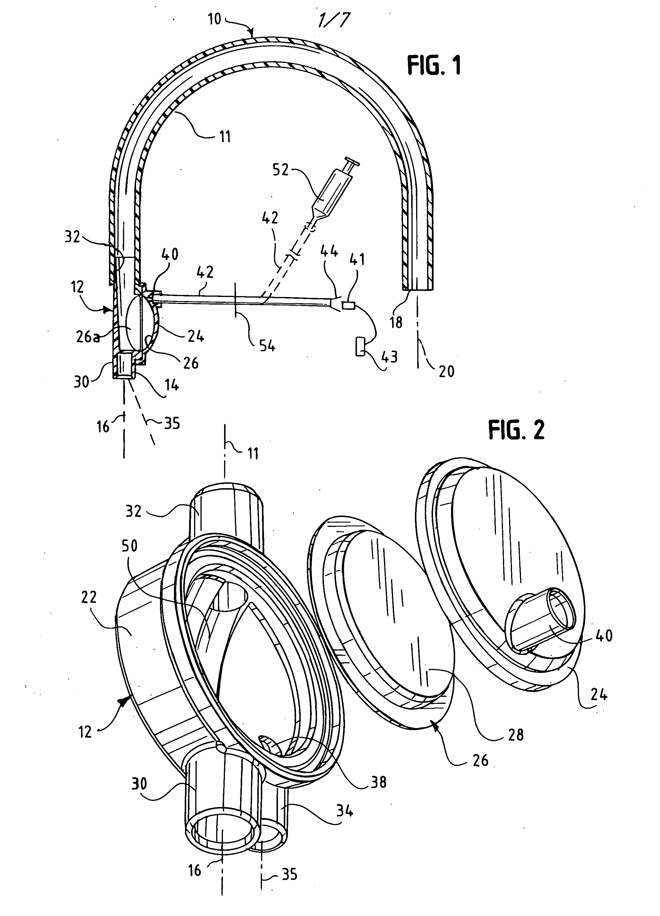
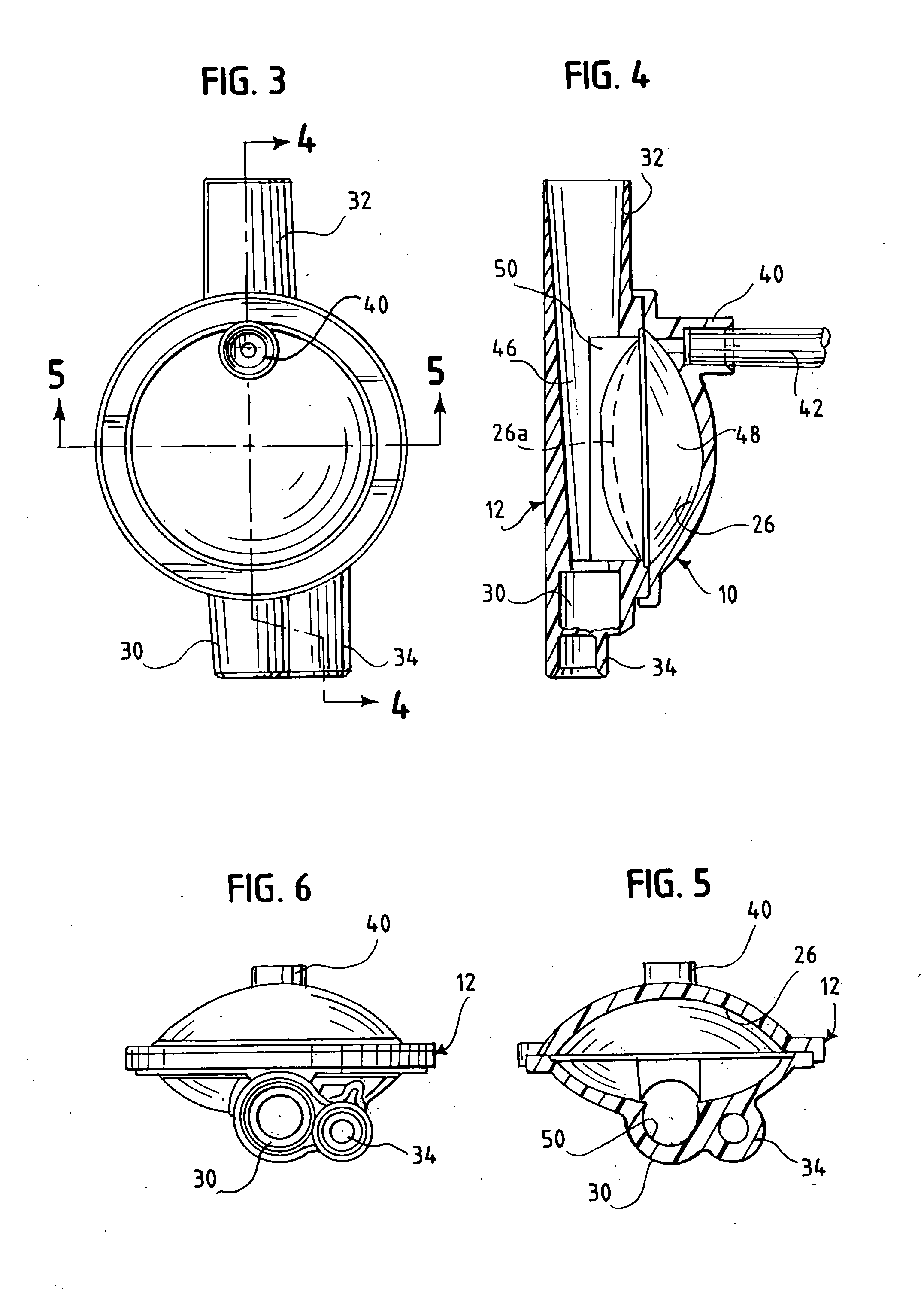
[0012] In accordance with this invention, a tubular blood flow set is provided which comprises a pressure sensing pod connected in flow-through relation to fluid flow tubing of said set, typically blood tubing. The pressure sensing pod defines a movable, flexible, impermeable diaphragm dividing the pod into two separate compartments. The fluid flow tubing communicates with one of the compartments for fluid flow through the compartment. The fluid flow tubing is isolated from the other of the compartments by the diaphragm. A pod connector carried on the pod communicates with the other of the compartments. In one embodiment of this invention a hollow-bore branch line is permanently attached to and communicates with the pod connector. The branch line is long enough, and terminates in a releasable connector such that it mates with the machine's pressure port. In another embodiment, the pod connector is releasable, and may be temporarily attached to a separate branch line bearing an appro...


PUM


Abstract

A tubular medical fluid flow set comprises a pressure sensing chamber connected in flow-through relation to fluid flow tubing of the set. The pressure sensing chamber defines a movable, flexible, impermeable diaphragm dividing the chamber into two separate compartments. The fluid flow tubing communicates with one of the compartments and is isolated from the other of the compartments. A port is carried on the chamber, the port having a seal therein, and communicating with the other of the compartments. Thus, the other of the compartments is hermetically sealed until the port is opened for connection with a pressure measuring device, to keep the flexible diaphragm in a desired, initial position prior to opening of the seal.

Description

BACKGROUND OF THE INVENTION [0001] Sets for extracorporeal blood handling, and also parenteral solution sets, generally require flow-through chambers, often called drip chambers, which, in use, utilize an upper liquid level of the medical liquid passing through it, with an air space on top. Such chambers generally have a permanently connected, branching, hollow-bore, flexible, branch line communicating with said air space for an air pressure line which connects via a reversible connector at its remote end to an equipment pressure port on the permanent equipment, which in turn communicates with a pressure monitor transducer for measuring air-pressure in the chamber as a surrogate for blood-pressure. A pressure-transmitting sterility barrier or diaphragm separates the sterile, disposable set and the unsterile permanent equipment. [0002] These sets generally need to be initially primed with saline or another parenteral solution, where the proper upper liquid level is provided in each d...

Claims


Application Information

Patent Timeline
Patent Type & Authority Applications(United States)
IPC IPC(8): A61M37/00
CPCA61M1/3639Y10T137/85978A61M1/3641A61M39/00F16L29/005A61M1/16A61M1/3627A61M1/3655
Inventor SCHNELL, WILLIAMBELL, DAVIDWILSON, KARENUTTERBERG, DAVID
Owner B BRAUN MEDICAL
Why Eureka
Try Eureka