Capacitive micromachined ultrasound transducer and methods of making the same

a micromachined ultrasound and transducer technology, applied in the field of diagnostic imaging, can solve the problems of reducing the parasitic capacitance and leakage current of the cmut cell, and reducing the yield of the devi

Inactive Publication Date: 2007-08-09
GENERAL ELECTRIC CO
View PDF6 Cites 134 Cited by
  • Summary
  • Abstract
  • Description
  • Claims
  • Application Information

AI Technical Summary

Benefits of technology

[0010] These and other features, aspects, and advantages of the present invention will become better understood when the following detailed description is read with reference to the accompanying drawings in which like characters represent like parts throughout the drawings, wherein:
[0011]FIG. 1 is a schematic flow chart illustrating steps involved in an exemplary method for making a capacitive micromachined ultrasound transducer cell according to certain embodiments of the present technique;
[0012]FIG. 2 is a top view of an exemplary capacitive micromachined ultrasound transducer array illustrating the location of contact pads and vacuum holes according to certain embodiments of the present technique;
[0013]FIG. 3 is a cross-sectional side view of the capacitive micromachined ultrasound transducer array of FIG. 2 cut along the line 3-3 cut;
[0014]FIG. 4 is a cross-sectional side view illustrating the capacitive micromachined ultrasound transducer array of FIG. 3 having top electrodes and metal or dielectric layer disposed thereon to seal the vacuum holes;
[0015]FIG. 5-9 is a schematic flow chart illustrating steps involved in making the capacitive micromachined ultrasound transducer cell according to certain embodiments of the present technique;
[0016]FIGS. 10-12 are schematic flow charts illustrating steps involved in exemplary methods for making vias in the carrier substrate for the capacitive micromachined ultrasound transducer cell according to certain embodiments of the present technique;
[0017]FIG. 13 is a top view of an exemplary capacitive micromachined ultrasound transducer array employing a carrier substrate having bottom electrodes and vias, where the vias are coupled to contact pads disposed on a surface of the carrier substrate according to certain embodiments of the present technique;
[0018]FIG. 14 is a top view illustrating an exemplary capacitive micromachined ultrasound transducer array after electrical isolation etch according to certain embodiments of the present technique;
[0019]FIG. 15 is a cross-sectional side view of the array of FIG. 14; and
[0020]FIG. 16 is a cross-sectional side view of the array of FIG. 15 further employing top electrodes according to certain embodiments of the present technique.

Problems solved by technology

This results in higher values of parasitic capacitance and leakage currents in a cMUT cell.
For example, while employing silicon substrate in a cMUT cell, the membrane and the support posts, which are typically oxides grown on the substrate, are coupled to one another by employing fusion bonding, which is done at temperatures above 900° C. If there is a mismatch in the coefficient of thermal expansions (CTEs) of the various layers of the cMUT cell, then processing at such high temperatures will tend to produce substrate warping and film delamination, which may reduce the device yield.
In addition to the low device yield, the thermal stress generated at the interface of each layer will change the boundary conditions of the membrane and thus make the membrane design (e.g. resonant frequency and collapsed voltage) unpredictable.
Some methods, such as high temperature annealing, will have to be used to alleviate the abovementioned high temperature induced effects but these processes require extra steps.

Method used


Image

  • Capacitive micromachined ultrasound transducer and methods of making the same
  • Capacitive micromachined ultrasound transducer and methods of making the same
  • Capacitive micromachined ultrasound transducer and methods of making the same

Examples


Embodiment Construction

[0021] In many fields, such as medical imaging and non-destructive evaluation, it may be desirable to utilize ultrasound transducers that enable the generation of high quality diagnostic images. High quality diagnostic images may be achieved by enhancing the sensitivity and performance of the capacitive micromachined ultrasound transducers (cMUTs) by reducing the parasitic capacitance and lowering the leakage current during operation as a transmitter and a receiver.

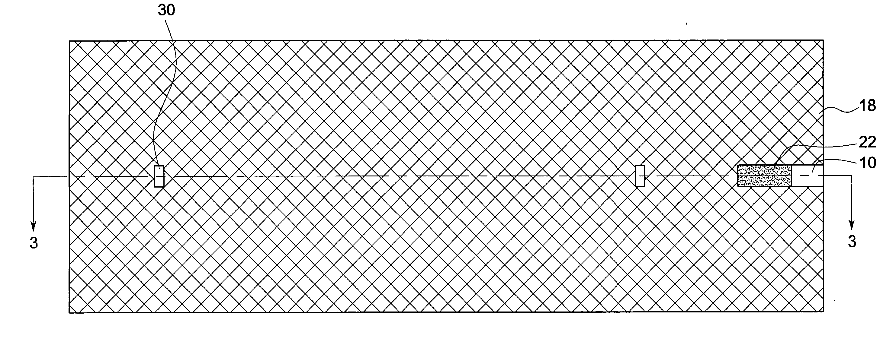
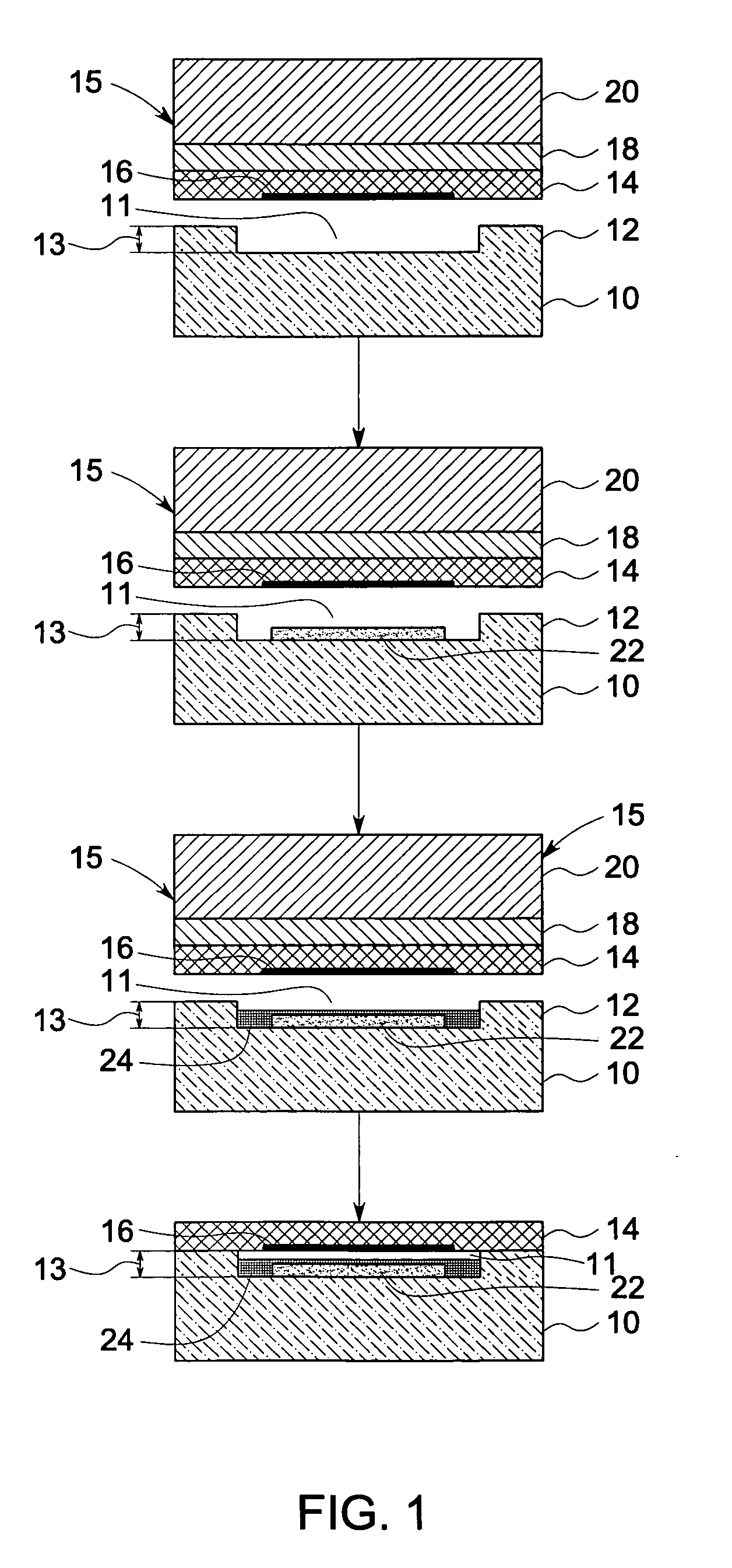
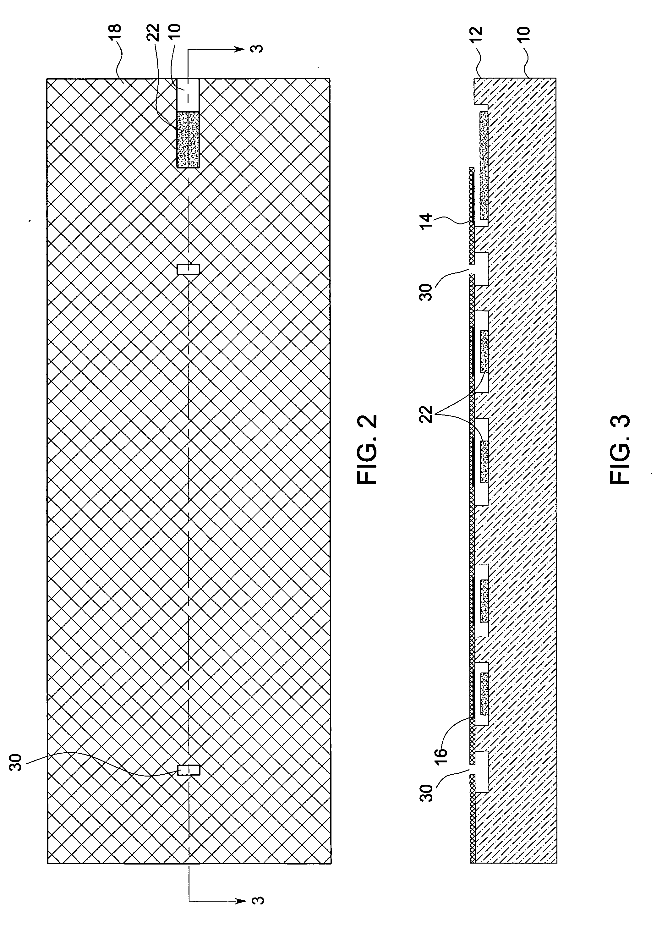
[0022] Turning now to FIG. 1, a schematic flow chart illustrating steps involved in a method of making a cMUT cell is illustrated. As will be appreciated by one skilled in the art, the figures are for illustrative purposes and are not drawn to scale. In the illustrated embodiment, the method begins by providing a carrier substrate 10. As will be described in detail below, in certain embodiments, the substrate 10 may include vias (not shown) to provide electrical communication between the two sides of the substrate 10. Th...


PUM

PropertyMeasurementUnit
bonding temperatureaaaaaaaaaa
temperaturesaaaaaaaaaa
thicknessaaaaaaaaaa

Abstract

A method of making a capacitive micromachined ultrasound transducer cell is provided. The method includes providing a carrier substrate, where the carrier substrate comprises glass. The step of providing the glass substrate may include forming vias in the glass substrate. Further, the method includes providing a membrane such that at least one of the carrier substrate, or the membrane comprises support posts, where the support posts are configured to define a cavity depth. The method further includes bonding the membrane to the carrier substrate by using the support posts, where the carrier substrate, the membrane and the support posts define an acoustic cavity.

Description

BACKGROUND [0001] The invention relates generally to the field of diagnostic imaging, and more specifically to capacitive micromachined ultrasound transducers (cMUTs) and methods of making the same. [0002] Transducers are devices that transform input signals of one form into output signals of another form. Commonly used transducers include light sensors, heat sensors, and acoustic sensors. An example of an acoustic sensor is an ultrasonic transducer, which may be implemented in medical imaging, non-destructive evaluation, and other applications. [0003] Currently, one form of an ultrasonic transducer is a capacitive micromachined ultrasound transducer (cMUT). A cMUT cell generally includes a substrate, a bottom electrode that may be coupled to the substrate, a membrane suspended over the substrate by means of support posts, and a metallization layer that serves as a top electrode. The bottom electrode, membrane, and the top electrode define the vertical extents of the cavity, whereas...

Claims


Application Information

Patent Timeline
Patent Type & Authority Applications(United States)
IPC IPC(8): G01H11/06H04R31/00G01R3/00
CPCA61B2562/028Y10T29/49005B06B1/0292
Inventor TIAN, WEI-CHENGSMITH, LOWELL SCOTTWEI, CHING-YEUWODNICKI, ROBERT GIDEONFISHER, RAYETTE ANNMILLS, DAVID MARTINCHU, STANLEY CHIENWUKWON, HYON-JIN
Owner GENERAL ELECTRIC CO
Why Eureka
Try Eureka