Air-cooled brake rotor system

Inactive Publication Date: 2007-08-09
KORM KEVIN
View PDF10 Cites 75 Cited by
  • Summary
  • Abstract
  • Description
  • Claims
  • Application Information

AI Technical Summary

Benefits of technology

[0051] It is yet another object of the present invention to provide an air-cooled disk brake rotor system that

Problems solved by technology

The array of grooves increases friction between a brake rotor and brake pads, and dec

Method used


Image

  • Air-cooled brake rotor system
  • Air-cooled brake rotor system
  • Air-cooled brake rotor system

Examples


Embodiment Construction

)

[0059] The detailed description set forth below in connection with the appended drawings is intended as a description of presently-preferred embodiments of the invention and is not intended to represent the only forms in which the present invention may be constructed and / or utilized. The description sets forth the functions and the sequence of steps for constructing and operating the invention in connection with the illustrated embodiments. However, it is to be understood that the same or equivalent functions and sequences may be accomplished by different embodiments that are also intended to be encompassed within the spirit and scope of the invention.

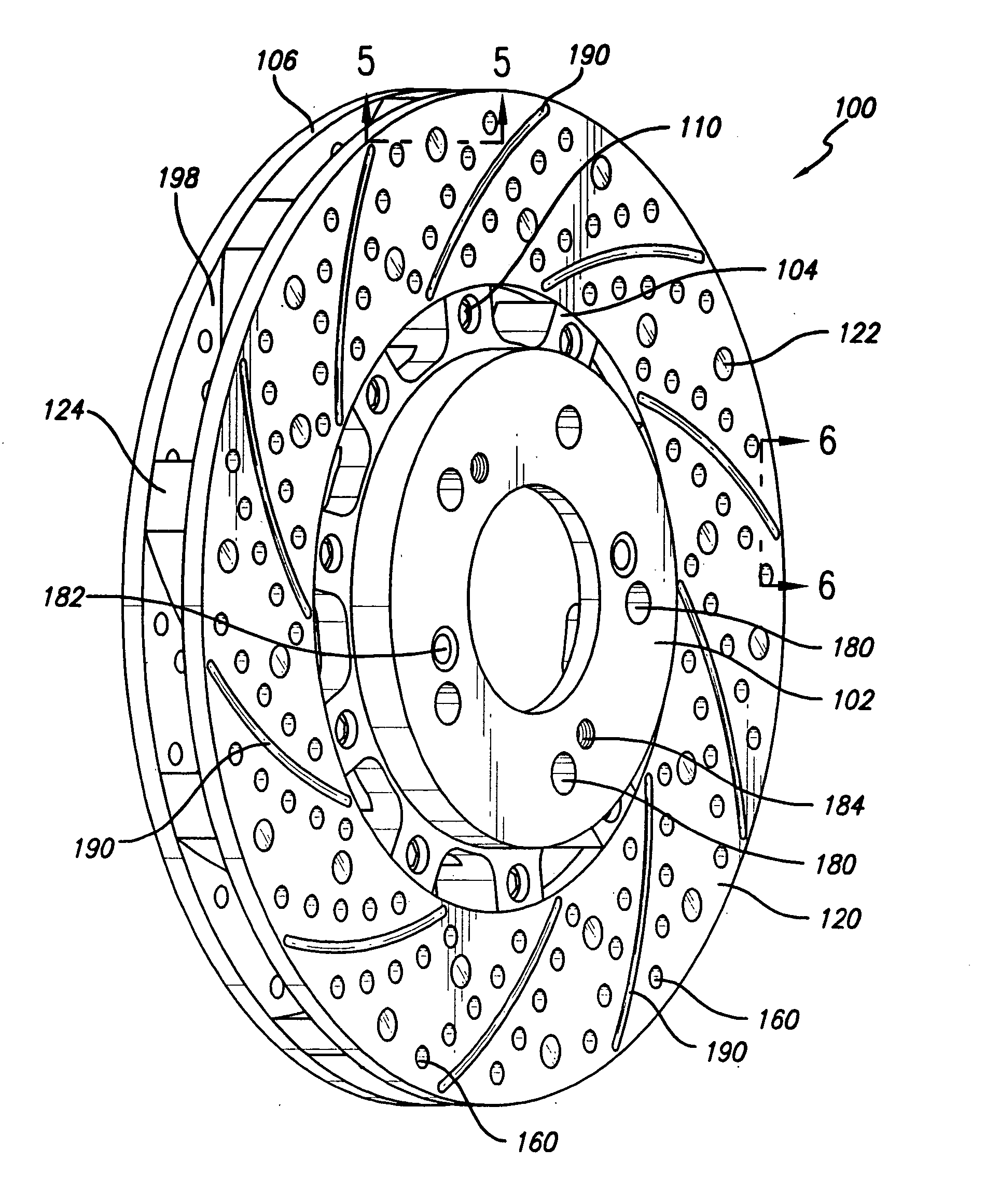
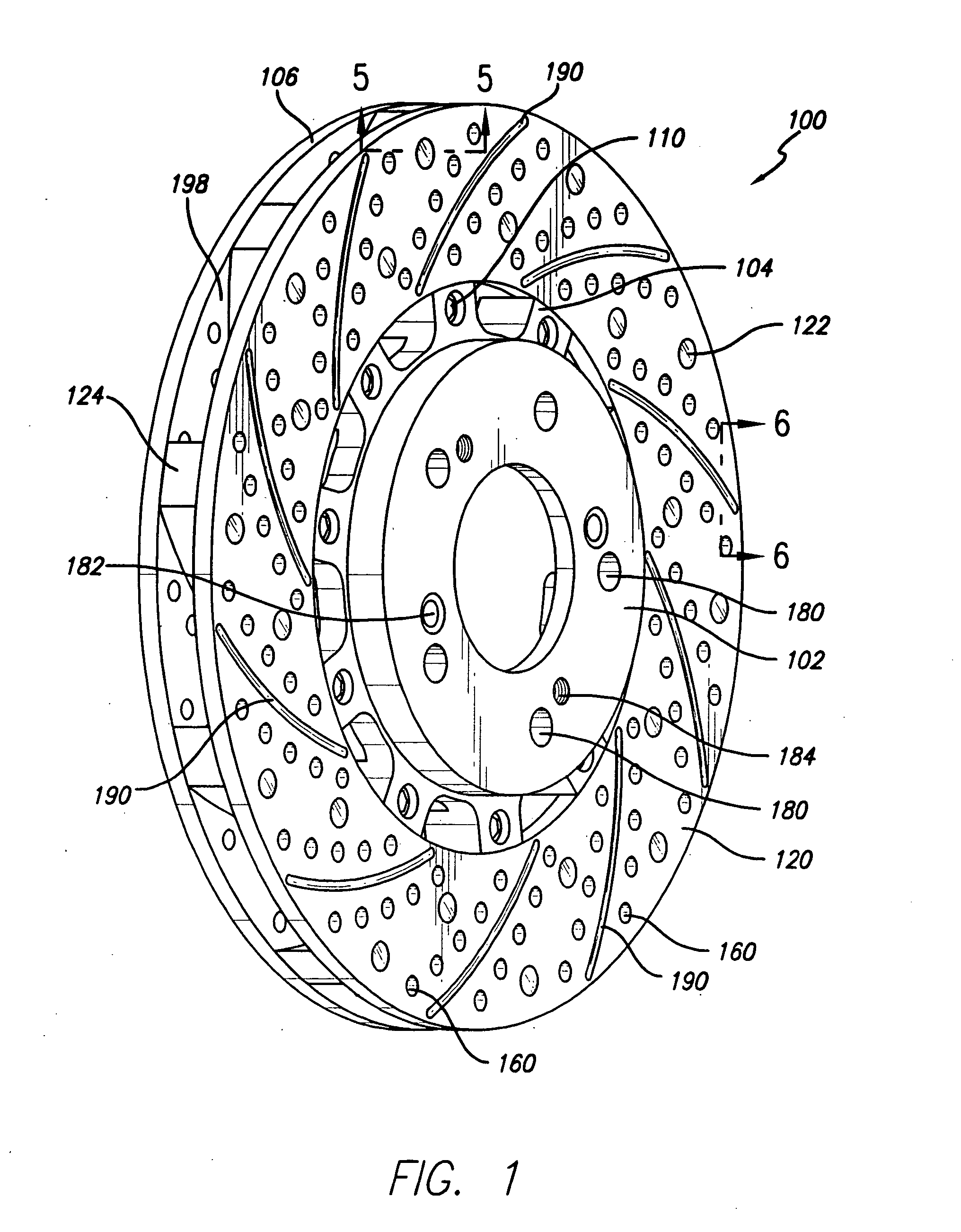
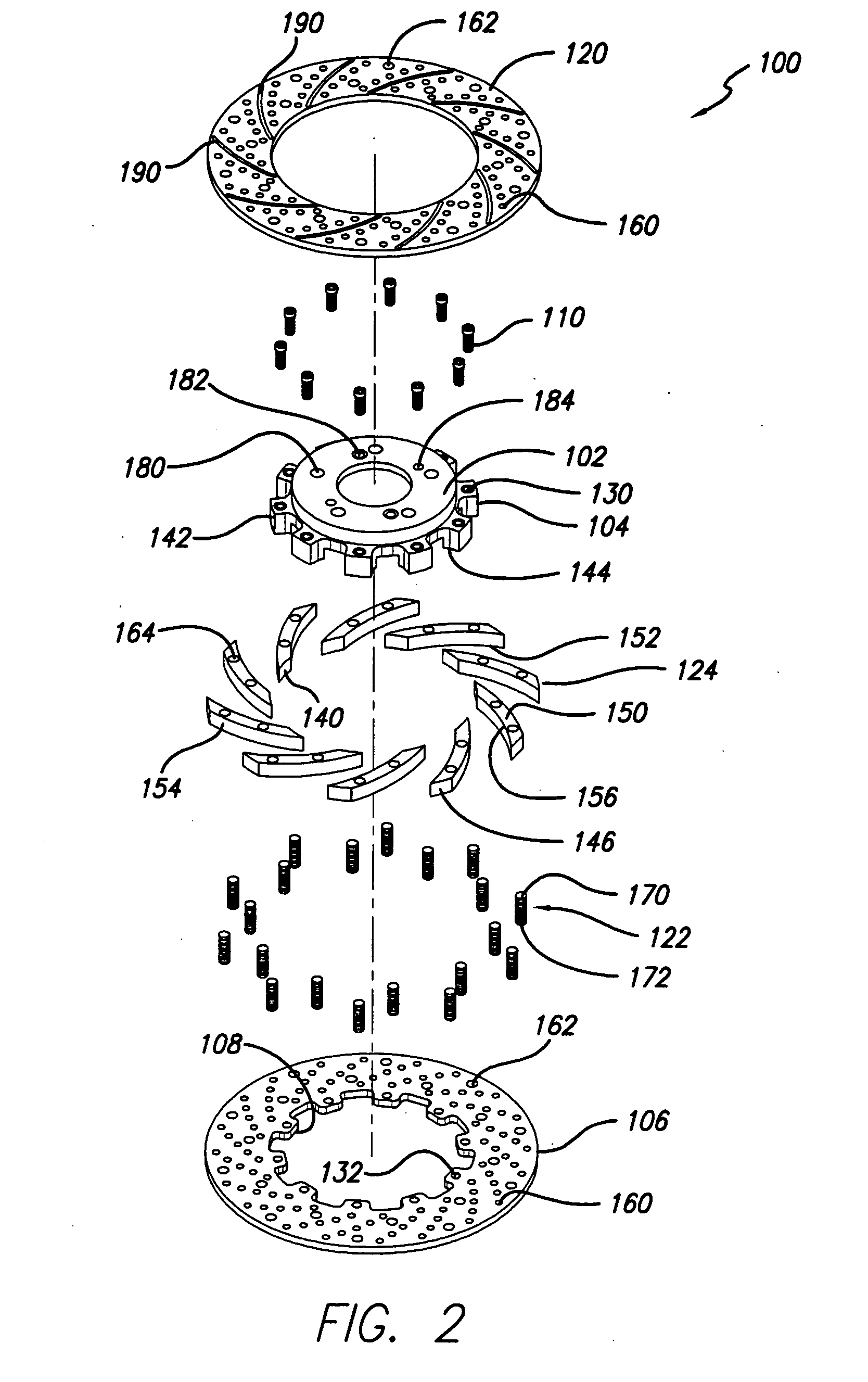
[0060] The present invention resides in an air-cooled brake rotor system having venting holes, inscribed slots, and spacers working in tandem in a co-axial dual plate rotor system to provide better braking and better cooling of the disk elements in a disk brake system. A central hub may be detachably attached to an inner rotor to whi...


PUM


Abstract

An air-cooled brake rotor system defining an inter-rotor disk slot through which spacers in the form of turbine or fan vanes propel air when the brake rotor system is turned. An inner disk brake rotor plate is attached to a hub which in turn may be attached to an axle on a vehicle such as an automobile. Pins having ends of opposite threading are used to connect the inner rotor to the outer rotor. The outer rotor is spaced apart from the inner rotor by means of spacers which are shaped to propel air through the slots defined between the two rotors. The spacers are also configured so that compression of the two rotors by a caliper system always serves to have a spacer beneath the area engaged by the brake pad to provide mechanical support for the rotor system. Each rotor generally has defined in it venting holes and inscribed debris-channeling slots in an arcuate, volute, or turbinate manner. An enhanced braking system experiencing lower heat retention is thereby attained.

Description

COPYRIGHT AUTHORIZATION [0001] Portions of the disclosure of this patent document may contain material which is subject to copyright and / or mask work protection. The copyright and / or mask work owner has no objection to the facsimile reproduction by anyone of the patent document or the patent disclosure, as it appears in the Patent and Trademark Office patent file or records, but otherwise reserves all copyright and / or mask work rights whatsoever. BACKGROUND OF THE INVENTION [0002] 1. Field of the Invention [0003] This invention relates to brakes, and more particularly to disk brakes for automotive and or other vehicles or the like that uses a pair of co-axial rotor planes that are particularly designed for rapid cooling by ambient air. [0004] 2. Description of the Related Art [0005] Brakes are well known in the art and are often used with a variety of vehicles including locomotives, automobiles, trucks, jet aircraft landing gear, bicycles, and the like. Particularly, disk brakes hav...

Claims


Application Information

Patent Timeline
IPC IPC(8): F16D65/12
CPCF16D65/128F16D65/847F16D2069/004F16D2065/1328F16D2065/136F16D2065/1316F16D2065/132
Inventor KORM, KEVIN
Owner KORM KEVIN
Why Eureka
Try Eureka