Reflective encoder with reduced background noise

Active Publication Date: 2007-08-09
AVAGO TECH INT SALES PTE LTD
View PDF4 Cites 16 Cited by
  • Summary
  • Abstract
  • Description
  • Claims
  • Application Information

AI Technical Summary

Benefits of technology

[0008] The present invention includes an encoder having a code strip and an emitter detector module. The code strip includes alternating reflective and opaque stripes. The emitter-detector module includes a light source that generates light and directs a portion of the generated light to the imaging element and a photodetector that generates a signal representing an intensity of light received by the photodetector having a linear polarization in a predetermined direction. The light source

Problems solved by technology

Hence, if there is an error in the code strip to detector distance, the image will be out of focus and errors will result.
Unfortunately, transmissive recorders require that two separate components, the light source and photodetector, be mounted and aligned with one another at the time of assembly of the encoder.
As the size of

Method used


Image

  • Reflective encoder with reduced background noise
  • Reflective encoder with reduced background noise
  • Reflective encoder with reduced background noise

Examples


Embodiment Construction

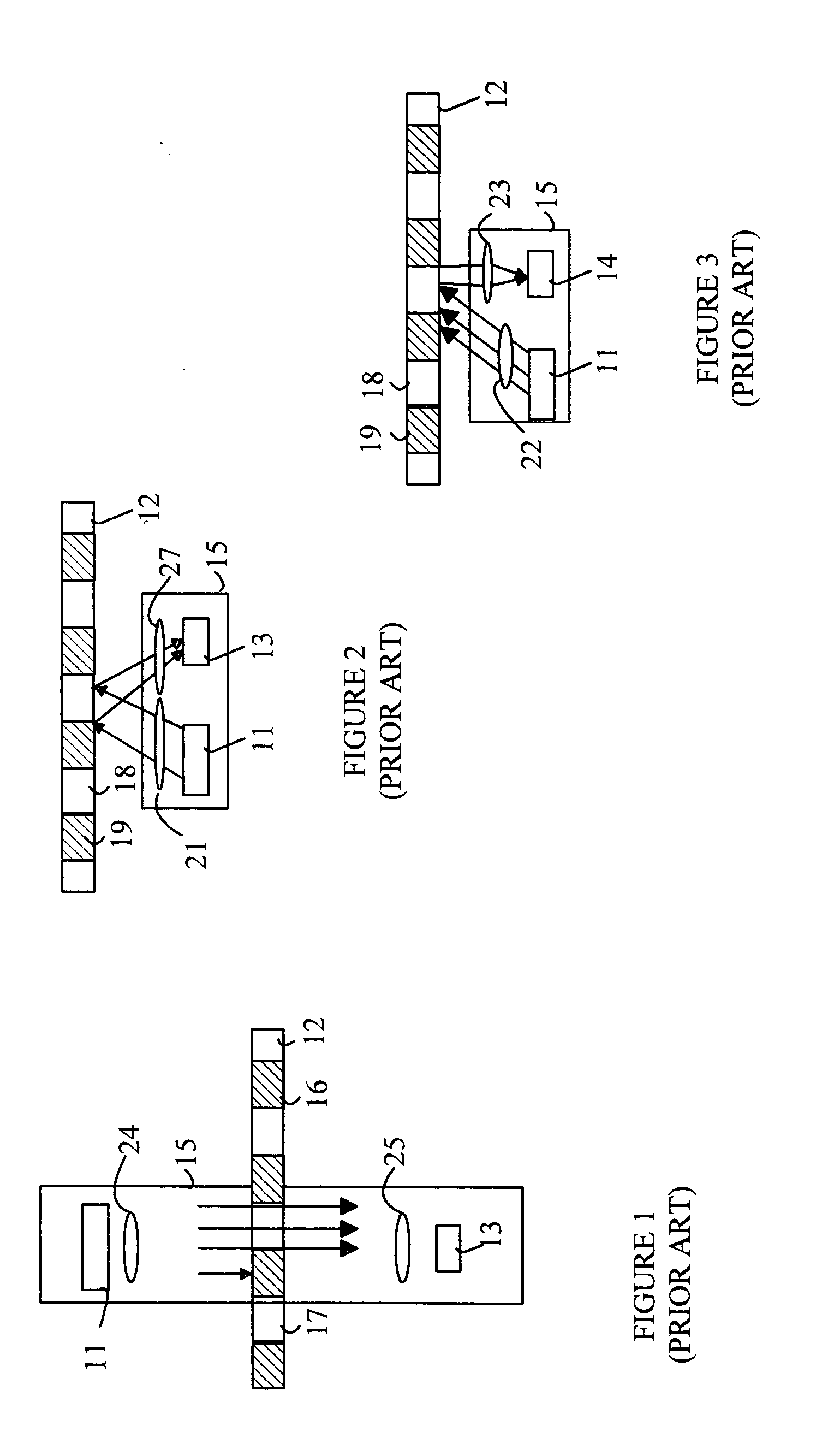
[0016] Refer now to FIGS. 1-3, which illustrate some typical encoder designs. The encoder can be divided into an emitter / detector module 15 and a code wheel or code strip. To simplify the terminology used herein, the term “code scale” is defined to include both linear code strips and circular code disks or code wheels. Module 15 includes an emitter 11 that illuminates a portion of the code scale 12. A detector 13 views the illuminated code scale. The emitter typically utilizes an LED as the light source. The detector is typically based on one or more photodiodes. FIG. 1 illustrates a transmissive encoder. In transmissive encoders, the light from the emitter is collimated into a parallel beam by a collimating optic such as lens 24. Code scale 12 includes opaque stripes 16 and transparent stripes 17. When code scale 12 moves between emitter 11 and detector 13, the light beam is interrupted by the opaque stripes on the code scale. The photodiodes in the detector receive flashes of ligh...


PUM


Abstract

An encoder having a code scale and an emitter detector module is disclosed. The code scale includes alternating reflective and opaque stripes. The emitter-detector module includes a light source that generates light and directs a portion of the generated light to the imaging element and a photodetector that generates a signal representing an intensity of light having a linear polarization in a predetermined direction received by the photodetector, the light source and the photodetector are encapsulated in a transparent medium, wherein there is a gap between the transparent medium and the code scale. The predetermined direction is chosen to reduce the intensity of light received by the photodetector that is reflected from an interface between the transparent medium and the gap. A polarization filter can also be included in the light source to further improve the rejection of the light reflected from the interface of the transparent medium and the gap.

Description

BACKGROUND OF THE INVENTION [0001] Encoders provide a measurement of the position of a component in a system relative to some predetermined reference point. Encoders are typically used to provide a closed-loop feedback system to a motor or other actuator. For example, a shaft encoder outputs a digital signal that indicates the position of the rotating shaft relative to some known reference position that is not moving. A linear encoder measures the distance between the present position of a moveable carriage and a reference position that is fixed with respect to the moveable carriage as the moveable carriage moves along a predetermined path. [0002] Optical encoders utilize a light source and a photodetector to measure changes in the position of an encoding disk or strip. In a transmissive encoder, the encoding disk includes a series of alternating opaque and transparent strips. The light source is located on one side of the code strip, and the photodetector is located on the other si...

Claims


Application Information

Patent Timeline
IPC IPC(8): G01D5/34
CPCG01D5/345
Inventor CHIN, YEE LOONG
Owner AVAGO TECH INT SALES PTE LTD
Why Eureka
Try Eureka