Surface acoustic wave device and electronic apparatus

a surface acoustic wave and electrode technology, applied in piezoelectric/electrostrictive/magnetostrictive devices, piezoelectric/electrostriction/magnetostriction machines, electrical apparatus, etc., can solve the problems of difficult to achieve higher frequencies for surface acoustic wave devices using reflection/inversion type idt electrodes, and achieve excellent frequency temperature characteristics, small frequency variation, and easy to achieve higher frequencies

Inactive Publication Date: 2007-08-09
COLUMBIA PEAK VENTURES LLC
View PDF5 Cites 34 Cited by
  • Summary
  • Abstract
  • Description
  • Claims
  • Application Information

AI Technical Summary

Benefits of technology

[0010]An advantage of the invention is to provide a surface acoustic wave device that shows an excellent frequency temperature characteristic and can readily achieve higher frequencies by using a single-type IDT electrode and utilizing the upper limit mode of the stop band as the oscillation frequency.
[0012]φ=0°, 110°≦θ≦140°, and 38°≦|ψ|≦44°, with the quartz substrate having cut angles and a surface acoustic wave propagation direction represented by Euler angles (φ, θ, ψ).
[0013]In addition the electrode thickness to wavelength should be set such that the relationship H/λ≧0.1796η3−0.4303η2+0.2071η+0.0682 is satisfied wherein the thickness of the IDT electrode is defined as H, the width of an electrode finger of the IDT electrode is defined as d, the pitch between the electrode fingers of the IDT electrode is defined as P, the wavelength of the surface acoustic wave is defined as λ, and where η=d/P.
[0014]The cut angles of the quartz substrate allow the surface acoustic wave propagation direction to be moved to a position distant from a symmetric position with respect to the quartz crystal in the quartz substrate. This makes it possible to utilize the upper limit mode of the stop band as the oscillation frequency of surface acoustic wave. Setting H/λ as described above allows the single-type IDT electrode to excite surface acous...

Problems solved by technology

However, a single-type IDT electrode on the ST-cut quartz substrate can excite no surface acoustic wave in the upper limit mode.
This places a burden on t...

Method used


Image

  • Surface acoustic wave device and electronic apparatus
  • Surface acoustic wave device and electronic apparatus
  • Surface acoustic wave device and electronic apparatus

Examples


first embodiment

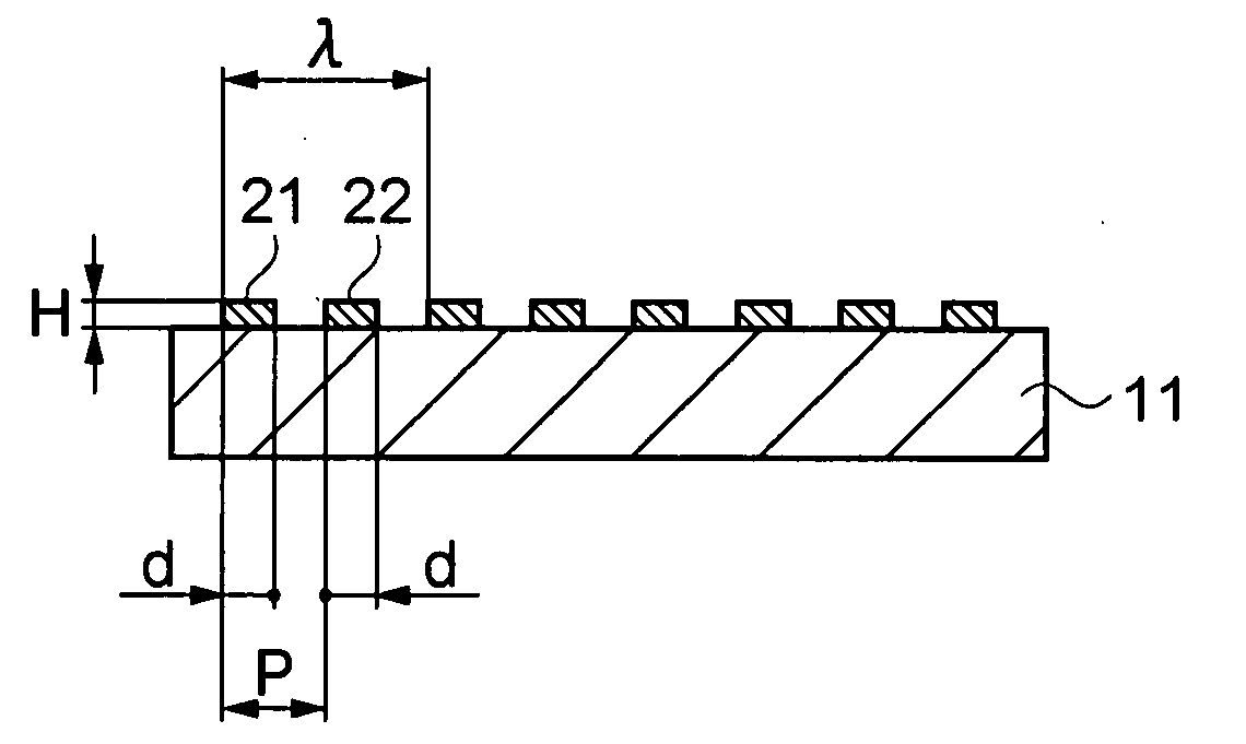
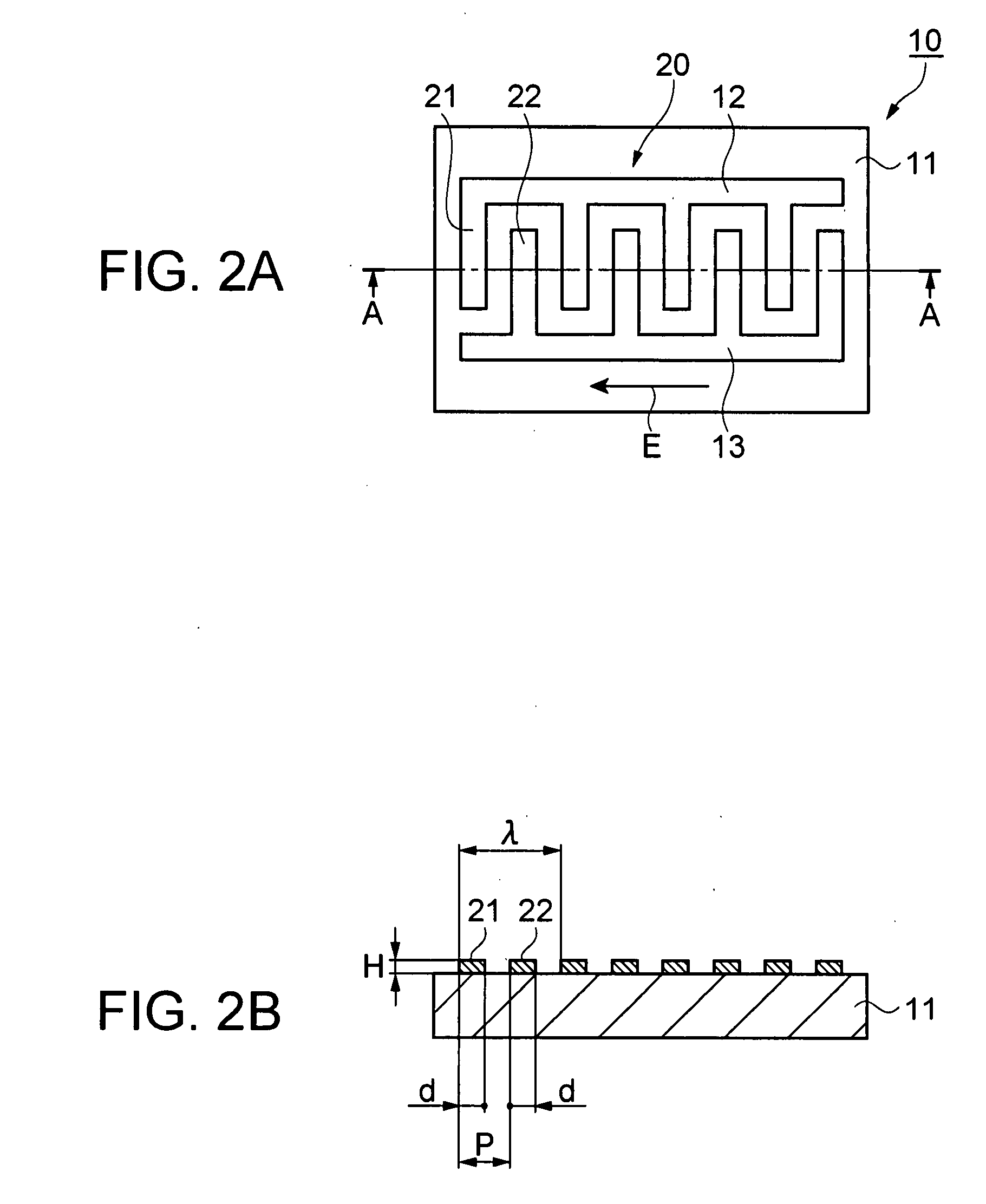
[0033]An embodiment of the invention will now be described with an SAW resonator as an example of a surface acoustic wave device. FIGS. 2A and 2B are schematic views of an SAW resonator including a single-type IDT electrode and serving as a surface acoustic wave device. FIG. 2A is a schematic plan view of the SAW resonator, and FIG. 2B is a schematic sectional view taken along line A-A of FIG. 2A.

[0034]A SAW resonator 10 has an IDT electrode 20 provided on a surface of a quartz substrate 11. The IDT electrode 20 includes an electrode 12 having multiple electrode fingers 21 and an electrode 13 having multiple electrode fingers 22. The electrode fingers 21 and 22 are disposed as if to be engaged with each other, and are formed with a thickness H and an electrode width d. Pitches P between the electrode fingers 21 and 22 are continuously formed in equal lengths. One electrode finger 21 and one electrode finger 22 are provided in one wavelength λ of a surface acoustic wave. The IDT elec...

second embodiment

[0053]Now a second embodiment will be described using as an example an SAW resonator including a reflector on both sides of the single-type IDT electrode described in the first embodiment. Generally, in a surface acoustic wave resonator, surface acoustic waves propagated outward of the IDT electrode are reflected off the reflector so as to trap the surface acoustic wave energy in the IDT electrode section. This makes it possible to obtain a less energy loss resonance characteristic.

[0054]FIGS. 6A and 6B are schematic views of the SAW resonator including the single-type IDT electrode and serving as a surface acoustic wave device; FIG. 6A is a schematic plan view of the SAW resonator, and FIG. 6B is a schematic sectional view taken along line B-B of FIG. 6A. In FIGS. 6A and 6B, the same elements as shown in FIG. 2 are given the same reference numbers.

[0055]The SAW resonator 10 has the IDT electrode 20 provided on a surface of the quartz substrate 11 and reflectors 14 and 15 on the sid...

third embodiment

[0064]FIG. 9 is a partial sectional view of an embodiment in which the SAW resonator serving as a surface acoustic wave device described in the first or second embodiment is packaged. An SAW resonator 31 is housed in a container 36 in such a manner that the SAW resonator 31 is fixed to the inside of the container 36. On the SAW resonator 31, a single-type IDT electrode 32 and a connection pad 33 to be connected to the single-type IDT electrode 32 are formed. The connection pad 33 on the SAW resonator 31 is electrically connected to a connection terminal 35 formed in the container 36 via a wire 34 made of Au. A lid 37 is put on the container 36 to keep the interior of the container 36 in a pressured-reduced atmosphere or an inert gas atmosphere. Thus, a packaged SAW resonator 30 is configured.

[0065]As described above, according to this embodiment, it is possible to obtain the packaged SAW resonator 30 that uses the single-type IDT electrode and utilizes the upper limit mode of the st...


PUM


Abstract

A surface acoustic wave device includes: a quartz substrate; and at least a single-type IDT electrode provided on a surface of the quartz substrate for exciting a Rayleigh surface acoustic wave in the upper limit mode of the surface acoustic wave stop band with the following relationships satisfied;
    • φ=0, 110°≦θ≦140°, and 38°≦|ψ|≦44°, when the quartz substrate cut angles and the surface acoustic wave propagation direction are represented by Euler angles (φ, θ, ψ), and wherein the electrode thickness relative to wavelength set such that
    • H/λ≧0.1796η3−0.4303η2+0.2071η+0.0682, with the thickness of the IDT electrode defined as H, the width of an electrode IDT finger defined as d, the pitch between the electrode fingers of the IDT electrode as P, the wavelength of the surface acoustic wave as λ, and where η=d/P.

Description

BACKGROUND[0001]1. Technical Field[0002]The present invention relates to a surface acoustic wave device using the upper limit mode of the stop band of Rayleigh surface acoustic waves.[0003]2. Related Art[0004]Surface acoustic wave devices such as SAW resonators or SAW filters, features higher frequencies, smaller sizes, and mass production capability, having widely been used in the field of communications. In particular, surface acoustic wave devices using a quartz substrate such as ST-cut quartz substrates shows high temperature stability featured by a quartz crystal so as to attain higher accuracy. As the use of portable communications apparatuses spread in recent years, those surface acoustic wave devices are further required to achieve higher frequencies and smaller sizes as well as higher temperature stability and thereby higher accuracy.[0005]It is known that two frequency solutions called “stop band” can be calculated with respect to a Rayleigh surface acoustic wave excited b...

Claims


Application Information

Patent Timeline
IPC IPC(8): H03H9/25
CPCH03H9/02551
Inventor KANNA, SHIGEO
Owner COLUMBIA PEAK VENTURES LLC
Why Eureka
Try Eureka