
Surface acoustic wave device and electronic apparatus

a surface acoustic wave and electronic equipment technology, applied in piezoelectric/electrostrictive/magnetostrictive devices, piezoelectric/electrostriction/magnetostriction machines, instruments, etc., can solve the problems of easy application of internal stress from the film to the electrodes, easy deterioration of the electrodes, and limited shortening the distance between each tooth in the comb-toothed electrode. , to achieve the effect o

Inactive Publication Date: 2007-08-09
SEIKO EPSON CORP
View PDF8 Cites 18 Cited by
  • Summary
  • Abstract
  • Description
  • Claims
  • Application Information

AI Technical Summary

Benefits of technology

The invention relates to a surface acoustic wave device with improved properties. The device includes a substrate, a piezoelectric film, an electrode, and two covering films. The first covering film is made of the same material as the piezoelectric film and covers the electrode, enclosing it within the piezoelectric film and reducing electrode deterioration. The second covering film is made of a material with higher thermal conductivity than amorphous SiO2 and improves heat radiation. The device also includes a hard layer on the substrate, which further reduces electrode deterioration and improves electric resistance. The invention also includes an electronic apparatus that includes the surface acoustic wave device.

Problems solved by technology

In the above two, there is a limit to shortening the distance between each tooth in a comb-toothed electrode due to microfabrication technique limitations.
However, JP-A-6-232677 above, for instance, has a problem in that, because it employs a configuration where comb-shaped electrodes are covered with a thin SiO2 film as shown in FIG. 2, etc., of the reference, the internal stress from the film is easily applied to the electrodes, and the electrodes break easily.
Furthermore, the above configuration decreases heat radiation, causing a problem of electrode deterioration due to thermal stress.
Furthermore, there is the problem of crystallinity in ZnO on the comb-toothed metallic electrodes.
The electrode deterioration described above leads to low electric resistance, resulting in deterioration of surface acoustic wave device properties.

Method used


Image

  • Surface acoustic wave device and electronic apparatus
  • Surface acoustic wave device and electronic apparatus
  • Surface acoustic wave device and electronic apparatus

Examples


embodiment 1

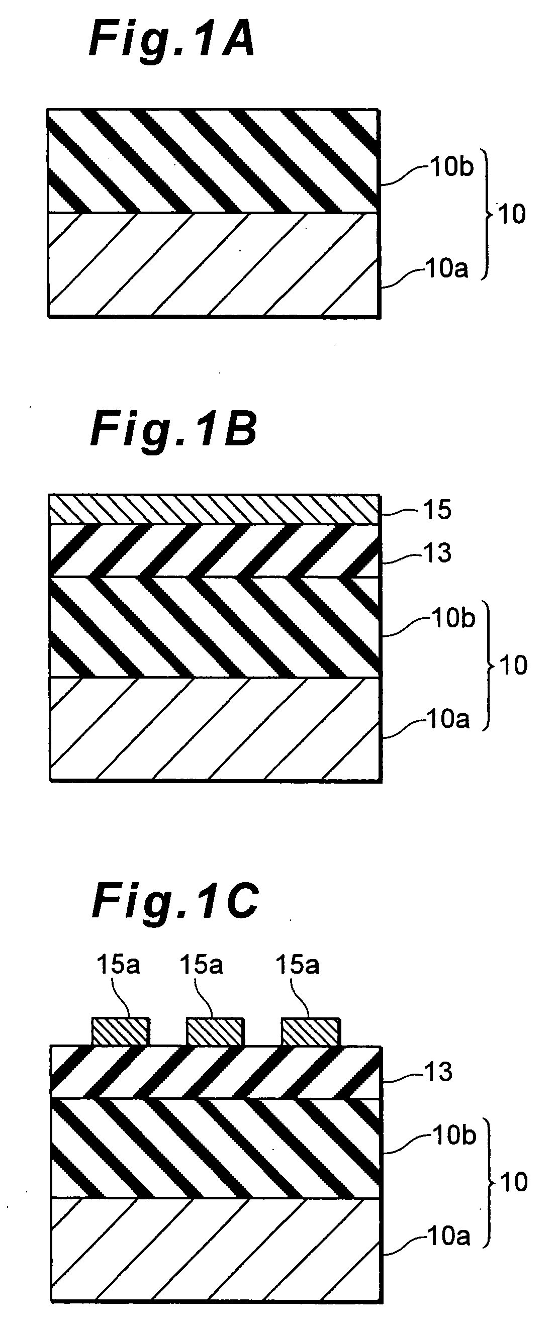
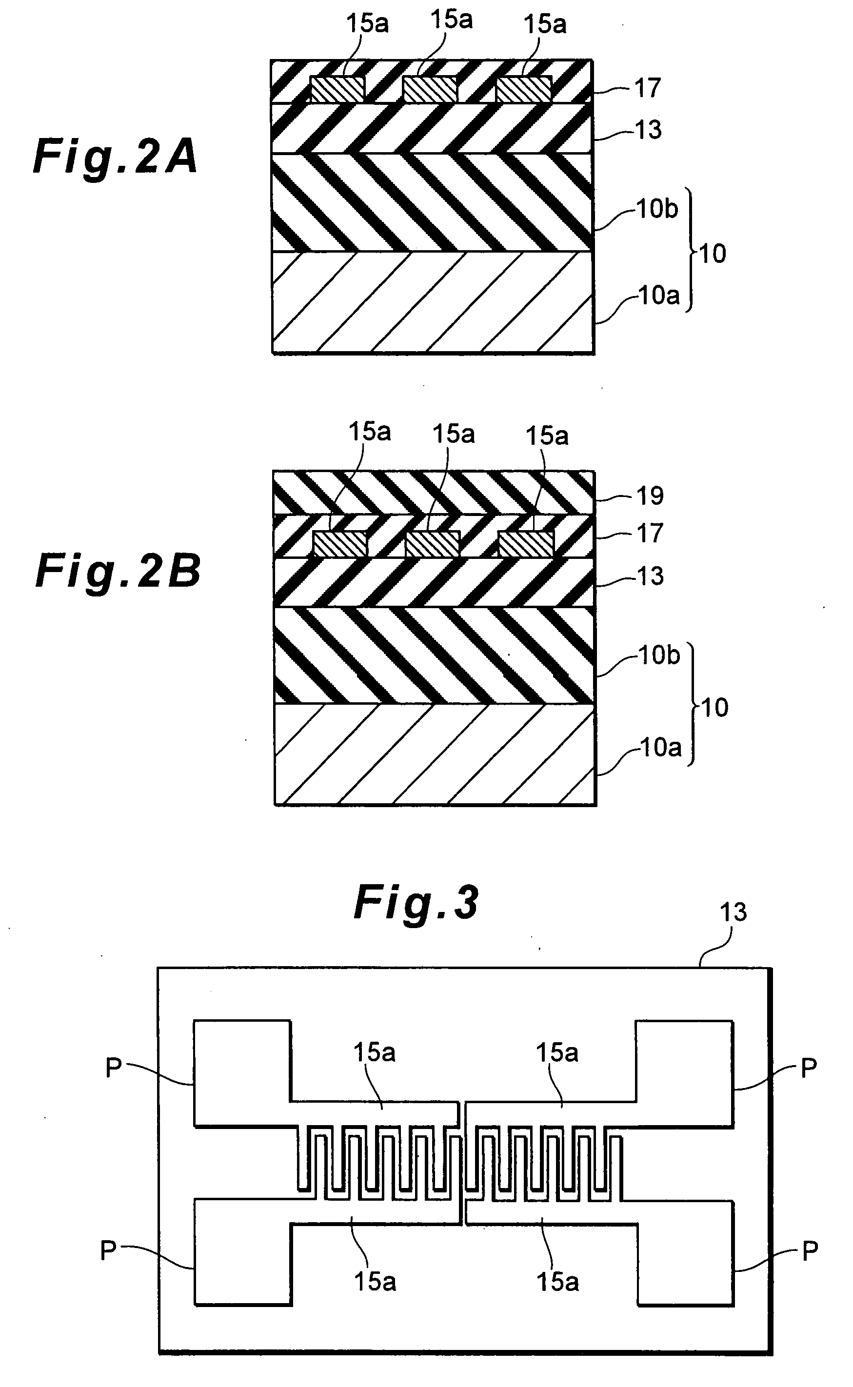
[0048]FIGS. 1 and 2 are sectional views showing the steps in a method for manufacturing a surface acoustic wave device according to this embodiment.

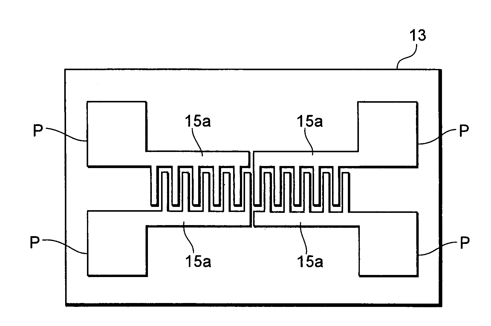
[0049]First, the configuration of a surface acoustic wave device according to this embodiment will be described. As shown in FIG. 2B, which illustrates the last step of the manufacturing method, the surface acoustic wave device according to this embodiment includes a substrate 10, a piezoelectric film 13, comb-toothed electrodes 15a, an electrode covering film 17, and a protection film 19.

[0050]The substrate 10 supports each component, and in this embodiment, a diamond substrate is used. The diamond substrate mentioned here is a substrate obtained by forming a diamond layer 10b on a silicon layer (silicon substrate) 10a.

[0051]Using the above substrate 10 with a hard layer (hard film) of diamond or similar on its surface, the propagation speed of a surface acoustic wave can be increased, and it becomes possible to generate higher frequen...

embodiment 2

[0082]In embodiment 2, the characteristics of a SAW resonator with the SiO2 / ZnO / diamond configuration explained in detail in embodiment 1 will be specifically explained. As explained before, the above SAW resonator has excellent stability with temperature at GHz frequencies. Using that SAW resonator, it is possible to realize a 2-3 GHz oscillator with low phase noise.

[0083]According to Lesson's Model, phase noise can be lessened by increasing electric power in an oscillating loop. In other words, in order to decrease phase noise, it is necessary to prepare a SAW resonator configuration that can endure an electricity increase.

[0084]The present inventors have found that electric resistance can be improved by placing ZnO above and below the IDTs, so that finding will be explained in detail below.

[0085]The following study was conducted to obtain a device that keeps a high phase velocity of 9000 m / s or larger and has a frequency-temperature characteristic with a peak temperature of 25° C...

embodiment 3

[0100]While the IDT (device) characteristics are improved in terms of reduction of stress in embodiments 1 and 2, the device characteristics are improved by enhancing heat radiation in this embodiment. Note that the same reference numerals are used for the same portions as in embodiment 1, and so their detailed explanation is omitted.

[0101]FIGS. 15 and 16 are sectional views showing the steps in a method for manufacturing a surface acoustic wave device according to this embodiment.

[0102]First, the configuration of a surface acoustic wave device according to this embodiment will be described. As shown in FIG. 16B, which illustrates the last step of the manufacturing method, the surface acoustic wave device according to this embodiment includes a substrate 10, a piezoelectric film 13, comb-toothed electrodes 15a, an electrode covering film 18, and a protection film 19.

[0103]The substrate 10 supports each component, and in this embodiment, a diamond substrate is used. The diamond subst...


PUM


Abstract

A surface acoustic wave device includes: (a) a substrate; (b) a piezoelectric film formed on top of the substrate; (c) an electrode for generating a surface acoustic wave formed on top of the piezoelectric film; (d) a first covering film formed on the electrode to cover the electrode, and made of the same material as that of the piezoelectric film; and (e) a second covering film formed on the first covering film.

Description

CROSS-REFERENCES TO RELATED APPLICATIONS[0001]The entire disclosure of Japanese Patent Application No. 2006-306318, filed on Nov. 13, 2006 and Japanese Patent Application No. 2006-31319, filed on Feb. 8, 2006 is expressly incorporated herein by reference.BACKGROUND[0002]1. Technical Field[0003]The present invention relates to a device utilizing a surface acoustic wave (SAW).[0004]2. Related Art[0005]A surface acoustic wave device (SAW filter) is an electro-mechanical conversion device that utilizes a surface wave traveling along the surface of a piezoelectric material, and it includes, as its basic configuration, a piezoelectric material and a pair of comb-toothed electrodes (IDTs: interdigital transducers) formed on top of the piezoelectric material. When an electric signal is applied to one of the comb-toothed electrodes, the piezoelectric material distorts, causing a surface acoustic wave to travel, and then the electric signal is output from the other comb-toothed electrode. In ...

Claims


Application Information

Patent Timeline
Patent Type & Authority Applications(United States)
IPC IPC(8): H03H9/25
CPCG06F3/0433H03H9/02944H03H9/02897H03H9/02574
Inventor KAWANO, SHUICHIFUJII, SATOSHI
Owner SEIKO EPSON CORP
Learn More