Light emitting device with optical enhancement structure

a light-emitting device and optical enhancement technology, which is applied in the direction of static indicating devices, discharge tubes luminescnet screens, instruments, etc., can solve the problems of insufficient light output efficiency, and insufficient enhancement, so as to minimize the total reflection of light

Inactive Publication Date: 2007-08-09
INNOLUX CORP
View PDF6 Cites 15 Cited by
  • Summary
  • Abstract
  • Description
  • Claims
  • Application Information

AI Technical Summary

Benefits of technology

[0009] The present invention solves the above-mentioned problems and provides a light emitting device with high light output efficiency. The present invention places a specially-designed optical enhancement structure along light output pathway of the light emitting device. By means of the special profile of the optical enhancement structure, the total internal reflection effect is reduced, thus enhancing light output efficiency of the organic light emitting device.
[0010] In one aspect of the present-invention, the light emerging surface of the optical enhancement structure is provided with a surface profile that reduces internal reflection. In one embodiment, the light emerging surface includes a central surface that is orthogonal to the normal and corner surfaces having profiles that are not orthogonal to the normal. The corner surface profiles may be at least one of an arcuate profile, a faceted profile, and a beveled profile. In another embodiment, light emerging surface include a convex surface, which may be an arcuate profile extending across the light emerging surface.
[0012] In one embodiment of the present invention, the light emitting device includes a plurality of pixels, each including a first electrode; an organic light emitting layer formed on the first electrode; a second electrode formed on the organic light emitting layer; and a first optical enhancement structure formed on the second electrode, such that light emitted from the organic light emitting layer can pass through the first optical enhancement structure and emerge from a first light emerging surface of the first optical enhancement structure. The first optical enhancement structure is a single structure for changing the normal angle of the first light emerging surface to increase light output efficiency.
[0015] In another aspect, the present invention uses an optical enhancement structure that directs diverging light from the light emitting layer along a path within the optical enhancement structure towards closer to the normal to emerge more light from the pixel to improve light output efficiency. The optical enhancement structure bends diverging light from the light emitting layer along a path within the optical enhancement structure, towards the normal of the pixel. In one embodiment, this may be accomplished with an optical enhancement structure having a refractive index profile that bends the diverging light from the light emitting layer towards the normal of the pixel. In another embodiment, the optical enhancement structure is structured with gradually changing refractive indices along the light output pathway of the organic light emitting device. The refractive indices decrease through the optical enhancement structure, towards the direction in which light emerges. The optical enhancement structure may be a single monolithic layer having a refractive index gradient, or comprise several layers of materials having different refractive indices. The optical enhancement structure may also serve additional functions, such as passivation of underlying layers, in addition to enhancing the light output. In other words, the optical enhancement structure could be combined with other layers such as passivation layer, cathode layers, etc. Thus, by diffracting light towards the normal of the pixel, more of the diverging light from the light emitting layer is directed to emerge from the pixel, thus enhancing light output efficiency.
[0017] In another aspect of the present invention, the optical enhancement layer further includes a light emerging surface having features for minimizing total reflection of light. In one embodiment, the light emerging surface includes an arcuate profile, a faceted profile, or a beveled profile.

Problems solved by technology

Light output efficiency in conventional organic light emitting devices (OLED) and polymer light emitting devices (PLED) is insufficient due to total internal reflection (TIR) and the waveguide effect.
The light output efficiency, however, is still not adequate with this more complex structure.
Thus, while light output efficiency is enhanced, the enhancement is not high enough.

Method used


Image

  • Light emitting device with optical enhancement structure
  • Light emitting device with optical enhancement structure
  • Light emitting device with optical enhancement structure

Examples


first embodiment

[0045]FIG. 26 is a cross-section view illustrating an organic light emitting device according to the present invention. For the sake of simplicity, FIG. 26 only shows a pixel region of the organic light emitting device. Further, there may be additional elements or components that are not shown in FIG. 26 but which may be present in the organic light emitting device.

[0046] Referring to FIG. 26, the pixel of the organic light emitting device includes a first electrode 11 formed on a glass substrate (not shown), an organic light emitting layer 12 formed on the first electrode 11, a second electrode 13 formed on the organic light emitting layer 12, and a first optical enhancement structure 14 formed on the second electrode 13. Light emitted from the organic light emitting layer 12 can pass through the first optical enhancement structure 14 and emerge from a first light emerging surface 14 a of the first optical enhancement structure 14. The first optical enhancement structure 14 is a si...

second embodiment

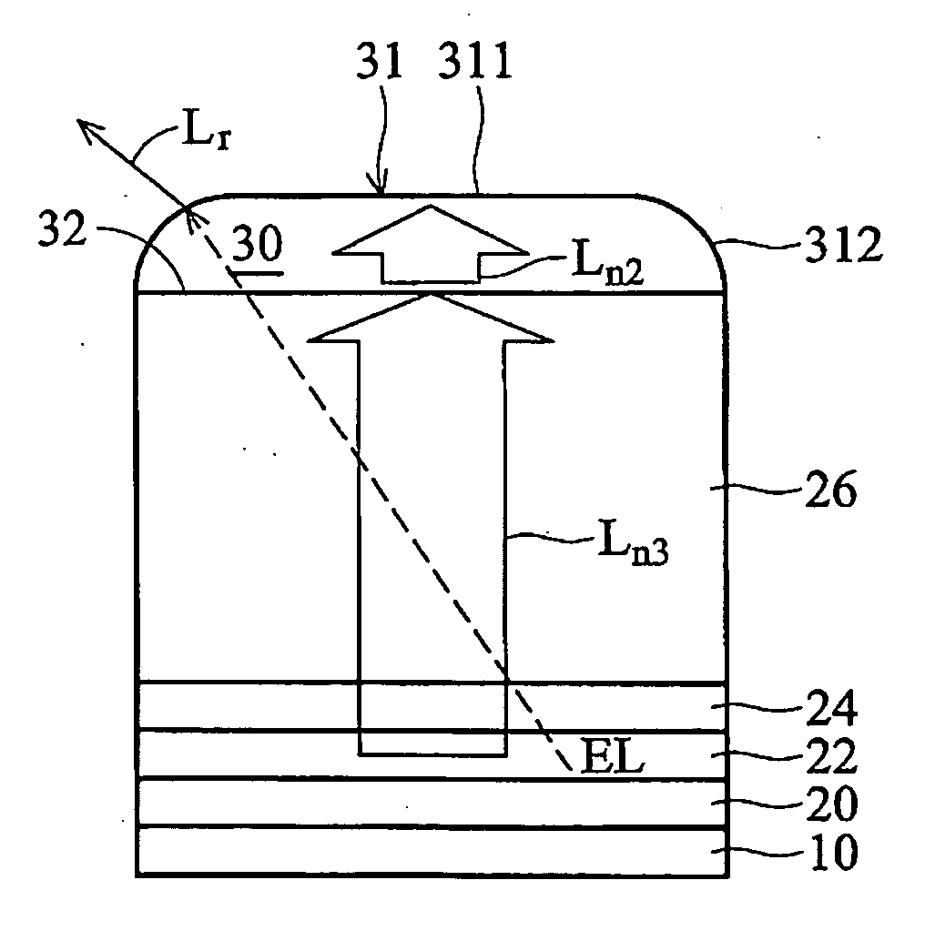
[0050]FIG. 5 is a cross-section of an organic light emitting device according to the present invention. The pixel includes a substrate 10, a reflective anode 20, an organic light emitting layer 22, a transparent cathode 24, and a passivation layer 26. Corresponding elements are the same as in FIG. 4 and detailed descriptions are thus omitted here. FIG. 5 differs from FIG. 4 in the first optical enhancement structure. In FIG. 5, the first optical enhancement structure 35 is formed on the passivation layer 26 and has a first light emerging surface 31, a bottom surface 32, and a sidewall 33. The first light emerging surface 31 includes a first surface 311 and a second surface 312. The first surface 311 has a flat profile, and the second surface 312 has an arcuate profile and is on the sides of the first surface 311. The second surface 312 connects the bottom surface 32 with the sidewall 33.

[0051] Similar to FIG. 4, the light beam totally reflected in the conventional OLED can refract a...

third embodiment

[0052]FIG. 6 is a cross-section of an organic light emitting device according to the present invention. The pixel includes a substrate 10, a reflective anode 20, an organic light emitting layer 22, a transparent cathode 24, and a passivation layer 26. Corresponding elements are the same as in FIG. 4 and detailed descriptions are thus omitted here. FIG. 6 differs from FIG. 4 in the first optical enhancement structure. In FIG. 6, the first optical enhancement structure 40 is formed on the passivation layer 26 and has a first light emerging surface 41 and a bottom surface 42. The first light emerging surface 41 includes a first surface 411 and a second surface 412. The first surface 411 has a flat profile, and the second surface 412 has a slanted or faceted profile and is on the sides of the first surface 411 to connect the bottom surface 42.

[0053] Similar to FIG. 4, the light beam on the edge that is totally reflected originally no longer satisfies the total reflection condition by me...


PUM


Abstract

A light emitting device with optical enhancement structure. The light emitting device includes a light emitting element and an optical enhancement structure. Some of the light from the light emitting element is emitted in a diverging manner. The optical enhancement structure is optically coupled to the light emitting element, said optical enhancement structure having a light emerging surface that includes a central surface that is orthogonal to the normal and corner surfaces having profiles that are not orthogonal to the normal. The optical enhancement structure is a single structure for changing the normal angle of the first light emerging surface to increase light output efficiency. The optical enhancement structure have an optical characteristic that directs diverging light from the light emitting element along a path within the optical enhancement structure in a direction towards a normal of the pixel.

Description

CROSS REFERENCE TO RELATED APPLICATIONS [0001] This application claims priority and is a continuation-in-part of pending U.S. patent application Ser. No. 10 / 939,017, filed on Sep. 9, 2004 and pending U.S. patent application Ser. No. 10 / 938,928, filed on Sep. 9, 2004. These applications are fully incorporated by reference as if fully set forth herein.BACKGROUND OF THE INVENTION [0002] 1. Field of the Invention [0003] The present invention relates to light emitting devices, and more particularly to an organic light emitting device including an optical enhancement structure. [0004] 2. Description of the Related Art [0005] Light output efficiency in conventional organic light emitting devices (OLED) and polymer light emitting devices (PLED) is insufficient due to total internal reflection (TIR) and the waveguide effect. Therefore, the actual light output efficiency is still very low although the internal quantum efficiency is near 100%. [0006]FIG. 2 is a cross-section of a conventional ...

Claims


Application Information

Patent Timeline
Patent Type & Authority Applications(United States)
IPC IPC(8): H01J1/62H01J63/04G09G3/20H01L51/52
CPCH01L51/5262H01J2211/44H01J1/62H01J1/70H10K50/85H10K50/858H10K2102/3026H01J63/04H10K50/80
Inventor WEI, AN-CHIYANG, HENG-LONGSHIEH, HAN-PING
Owner INNOLUX CORP
Why Eureka
Try Eureka