
Vehicle light

Inactive Publication Date: 2007-08-09
STANLEY ELECTRIC CO LTD
View PDF2 Cites 11 Cited by
  • Summary
  • Abstract
  • Description
  • Claims
  • Application Information

AI Technical Summary

Benefits of technology

[0024]Therefore, in view of the above-described and other issues and characteristics, according to an aspect of the disclosed subject matter, a vehicle light can be configured to have a simple structure which can suppress the deterioration of the light emitting quality of a semiconductor light emitting device and can prevent the aged deterioration of a coating on the reflection surface of a reflector.

Problems solved by technology

Since such a silicon resin has a certain degree of hygroscopicity, the silicon resin may deteriorate due to absorption of moisture during long-term use.
That is, the light emitting quality may deteriorate.
Thus, it was found that deterioration due to humidity was significant.
Similarly, it was found that the deterioration due to humidity was significant.
Such a problem may occur not only when a light source is a resin-encapsulated LED but also when a light source is selected from one of other types of semiconductor light emitting devices such as semiconductor laser devices, etc.
When such reflectors are employed, the surface thereof may oxidize or sulphidize during long-term use.
In particular, when the surface is sulphidized, the appearance color may change which can result in a reduction in reflectivity.

Method used


Image

  • Vehicle light
  • Vehicle light
  • Vehicle light

Examples


Embodiment Construction

[0046]Hereinafter, exemplary embodiments of the disclosed subject matter will be described in detail with reference to FIGS. 2 to 4. The exemplary embodiments described hereinafter are specific examples in accordance with principles of the disclosed subject matter, and thus various technical features are associated therewith. However, the scope of the disclosed subject matter is not limited to the exemplary embodiments.

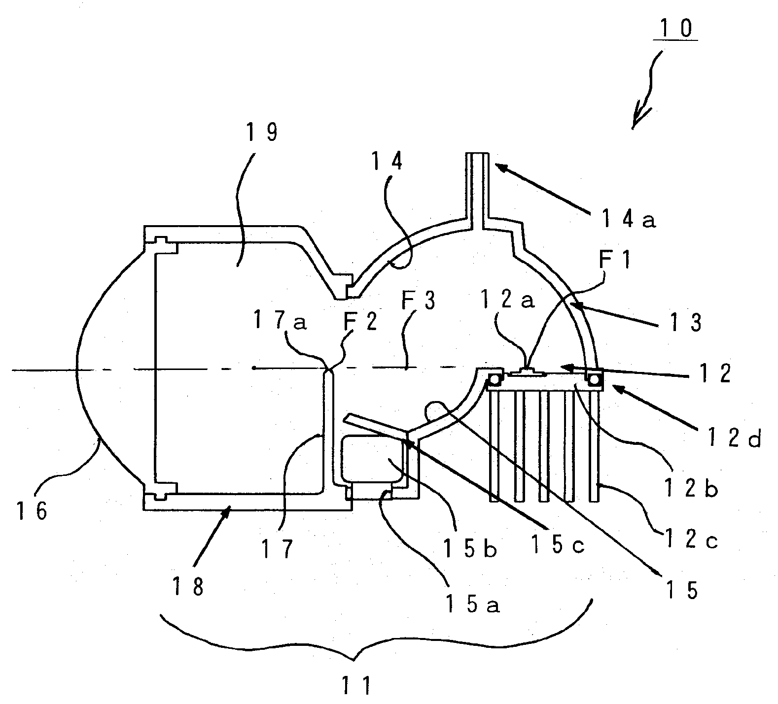
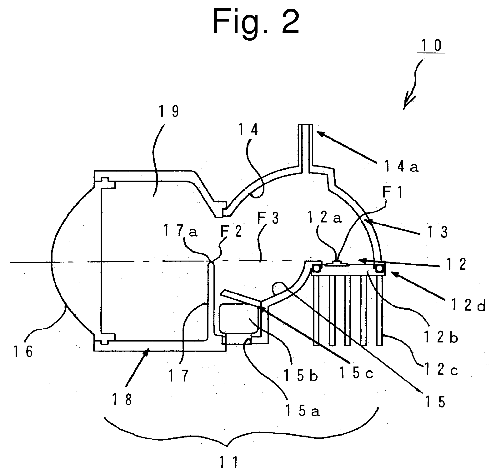
[0047]FIG. 2 shows the configuration of an exemplary embodiment of a vehicle light made in accordance with principles of the disclosed subject matter.

[0048]In FIG. 2, a vehicle light 10 may be an LED headlight for an automobile and be configured to include at least one (one in the illustrated example) projector type optical unit 11.

[0049]The optical unit 11 is configured to include: an LED light source 12; a first reflector 13; a second reflector 14; a third reflector 15; a projection lens 16; a shutter 17; and a lens holder 18. The optical unit 11 can have a configur...


PUM

PropertyMeasurementUnit
Pressureaaaaaaaaaa
Flow rateaaaaaaaaaa
Transparencyaaaaaaaaaa

Abstract

A vehicle light that includes a semiconductor light emitting device can have a simple structure which suppresses deterioration of the light emitting quality of the device. The vehicle light can be configured to prevent aging and / or deterioration of components, such as a vapor deposited silver coating on the reflection surface of a reflector of the light. The vehicle light can also include a projector type optical unit that has the following components: a semiconductor light emitting device; a reflector which surrounds the semiconductor light emitting device from a rear side such that light emitted from the semiconductor light emitting device is reflected in a forward direction; and a projection lens which projects light being directly from the light emitting device or after reflected by the reflector in the forward direction. Furthermore, a space around the semiconductor light emitting device of the optical unit can be hermetically sealed from the outside atmosphere. A sealing member can be used to form the sealed space.

Description

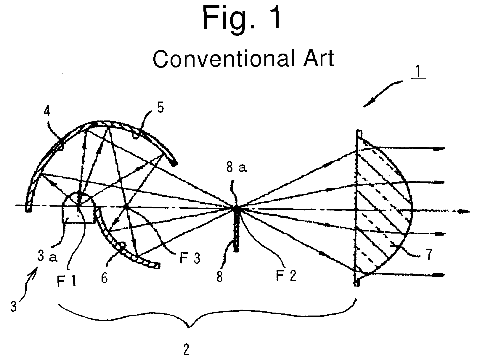
[0001]This application claims the priority benefit under 35 U.S.C. §119 of Japanese Patent Application No. 2006-026575 filed on Feb. 3, 2006, which is hereby incorporated in its entirety by reference.BACKGROUND[0002]1. Field[0003]The disclosed subject matter relates to a vehicle light which employs a semiconductor light emitting device as a light source.[0004]2. Description of the Related Art[0005]In recent years, the output power of a semiconductor light emitting device such as an LED has increased, and the luminance thereof has increased accordingly. With the increase in the luminance, the development of an LED and the like used as a light source for a vehicle light is continuously in progress.[0006]Japanese Patent Application Laid-Open No. 2005-276805 discloses a vehicle light which employs a semiconductor light emitting device such as an LED, for example, as a light source. An example of the configuration of such a vehicle light is shown in FIG. 1.[0007]In FIG. 1, a vehicle ligh...

Claims


Application Information

Patent Timeline
IPC IPC(8): F21V7/00H01L33/44H01L33/58H01L33/60
CPCF21S48/1159F21S48/1216F21S48/1388F21Y2101/02F21S48/145F21S48/335F21V7/22F21S48/1394F21Y2115/10F21S41/255F21S41/321F21S41/37F21S41/43F21S45/10F21S45/50F21S45/60F21S41/365F21V7/24F21V7/28F21S45/48F21S41/148
Inventor KOIKE, TERUOOMORI, SHINYAYAMADA, MITSUOUMEYAMA, TATSUYA
Owner STANLEY ELECTRIC CO LTD
Learn More