Method of controlling output of ultrasonic speaker, ultrasonic speaker system, and display device

Inactive Publication Date: 2007-08-09
SEIKO EPSON CORP
View PDF3 Cites 25 Cited by
  • Summary
  • Abstract
  • Description
  • Claims
  • Application Information

AI Technical Summary

Benefits of technology

[0037]Thus, in the ultrasonic speaker used in the display device according to the aspect of the invention, the band-corresponding volume setting units that respectively set the volume of sounds radiating from ultrasonic transducers, which are provided corresponding to respective frequency bands, are provided corresponding to the respective frequency bands and the overall volume setting unit that in common sets the volume of sounds radiating from the ultrasonic transducers provided corresponding to respective frequency bands is also prov

Problems solved by technology

As a result, the satisfactory quality of sound is not obtained.
Further, in the case when sound waves are emitted from ultrasonic transducers provided corresponding to respective frequency bands, it is an issue that a large amount of power is consumed as compared wit

Method used


Image

  • Method of controlling output of ultrasonic speaker, ultrasonic speaker system, and display device
  • Method of controlling output of ultrasonic speaker, ultrasonic speaker system, and display device
  • Method of controlling output of ultrasonic speaker, ultrasonic speaker system, and display device

Examples


first embodiment

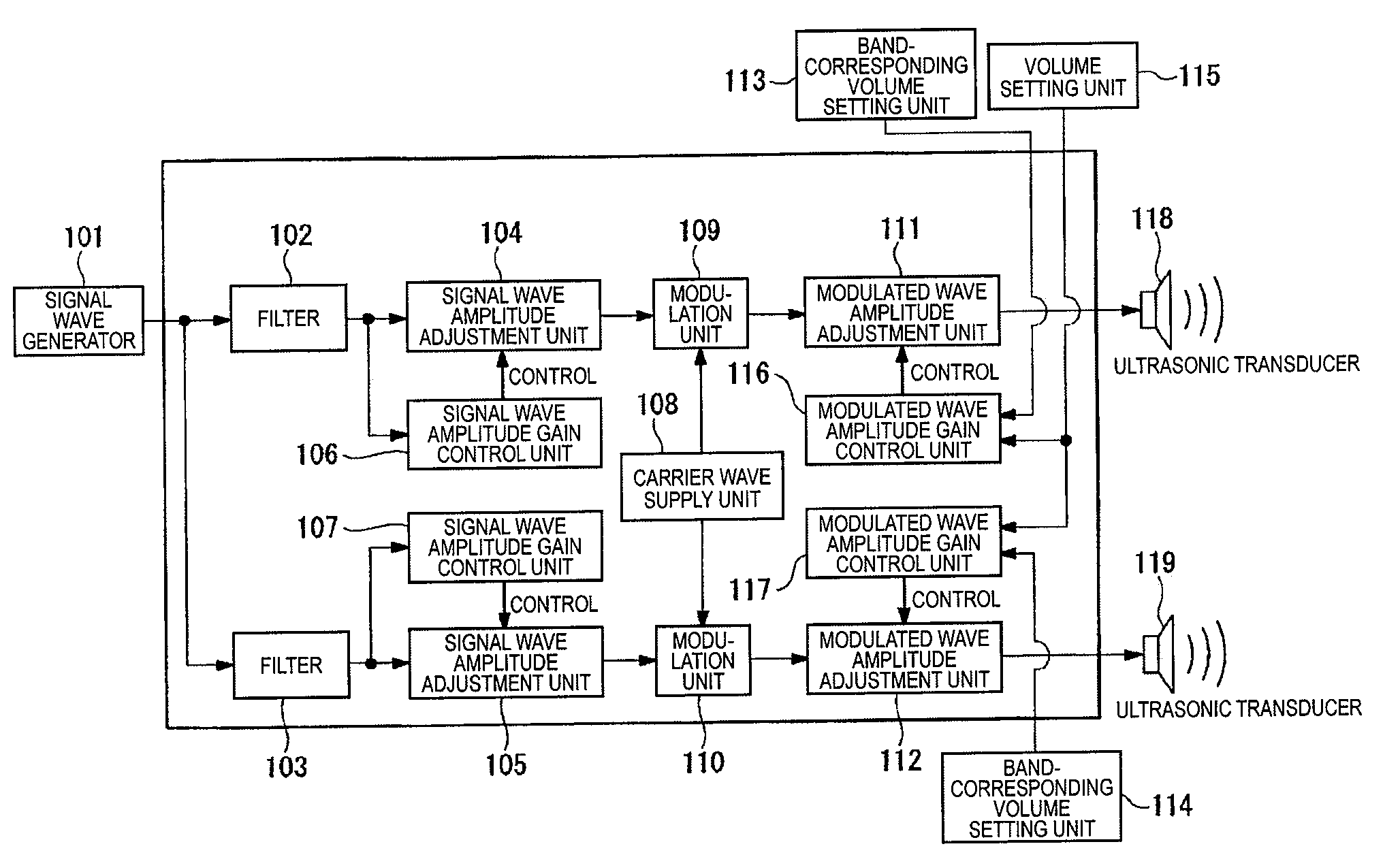
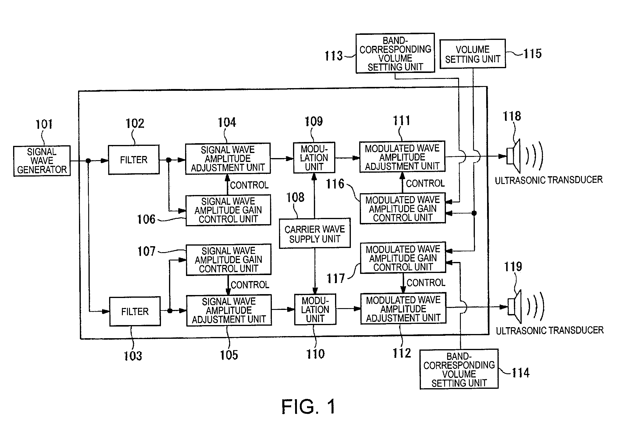
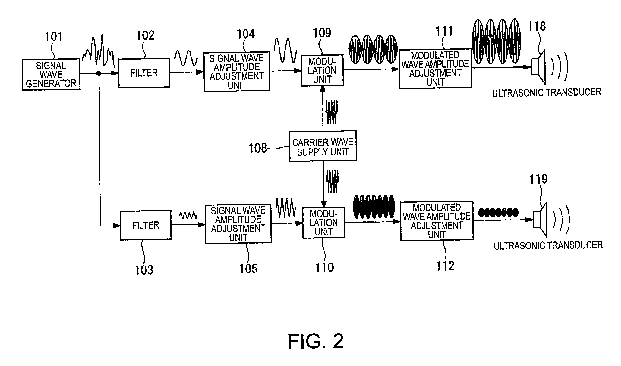
[0061]The configuration of an ultrasonic speaker system according to an embodiment of the invention is shown in FIG. 1. In addition, FIG. 2 is a view schematically illustrating waveforms of signals having passed through respective constituent blocks in the configuration of the ultrasonic speaker system shown in FIG. 1. Here, even though some of constituent components shown in FIG. 1 are not intentionally shown in FIG. 2 for the sake of convenience, all of the constituent components shown in FIG. 1 are needed when actually using the invention. The ultrasonic speaker system according to the embodiment of the invention is an example of a system in which an adjustment can be made such that volume in the middle and low frequency band is output to the maximum, an adjustment to proper sound quality and volume with respect to audio signals can be easily made, it is possible to prevent modulated waves from being overmodulated, and it is possible to prevent an overvoltage from being applied t...

second embodiment

[0105]In the first embodiment of the invention, an example of the ultrasonic speaker system has been described. In the second embodiment of the invention, an example of an ultrasonic speaker system using a push-pull type electrostatic transducer will be described.

[0106]FIGS. 9A and 9B are views illustrating an example of an electrostatic transducer driven in an ultrasonic speaker system according to the embodiment of the invention. In particular, the electrostatic transducer has a structure suitable for being used as a transducer of an ultrasonic speaker. FIG. 9A illustrates a cross-sectional surface of an electrostatic transducer 330. The electrostatic transducer 330 includes: a vibrating film 340 having a conductive layer; and a pair of fixed electrodes including a front-surface-side fixed electrode 331A and a bottom-surface-side fixed electrode 331B (referred to as a fixed electrode 331 in the case of indicating both the front-surface-side fixed electrode 331A and the bottom-surf...

third embodiment

[0117]Next, it will be described about a display device using the ultrasonic speaker according to the embodiment of the invention, that is, a display device using an ultrasonic speaker that can be adjustable such that sounds in the middle and low frequency band are output to the maximum and can easily make an adjustment to proper sound quality and volume with respect to audio signals.

[0118]Hereinafter, a projector, which is an example of the display device according to the embodiment of the invention, will be described. In addition, the display device according to the embodiment of the invention is not limited to the projector but may be applied to various display devices that reproduce sound and image.

[0119]FIG. 11 illustrates a state in which the projector (display device) according to the embodiment of the invention is used. As shown in FIG. 11, a projector 401 is disposed at a rear side of a viewer 403. The projector 401 is configured such that an image is projected onto a scree...


PUM


Abstract

A method of controlling an output of an ultrasonic speaker that reproduces audible-frequency-band signal sounds by modulating carrier waves with audible-frequency-band signal waves output from a signal source and driving an ultrasonic transducer with the modulated waves includes: dividing the audible-frequency-band signal waves into a plurality of frequency bands; separately adjusting amplitudes of the signal waves and amplitudes of the modulated waves in the respective frequency bands; and driving a plurality of ultrasonic transducers provided corresponding to the respective frequency bands with the modulated waves generated corresponding to the respective frequency bands. Band-corresponding volume setting data, which is used to set volume of the ultrasonic transducers corresponding to the respective frequency bands by means of a plurality of band-corresponding volume setting units provided corresponding to the respective frequency bands, and overall volume setting data, which is used to set volume in common with respect to the plurality of ultrasonic transducers by means of an overall volume setting unit, are provided. Gains of modulated wave amplitude adjustment units that adjust the amplitudes of the modulated waves in the respective frequency bands are determined corresponding to the respective frequency bands on the basis of a combination of the band-corresponding volume setting data and the overall volume setting data.

Description

BACKGROUND[0001]1. Technical Field[0002]The present invention relates to a method of controlling an output of an ultrasonic speaker that drives ultrasonic transducers with modulated signals obtained by modulating ultrasonic-frequency-band carrier waves with audible-frequency-band sound waves (for example, audio signals), an ultrasonic speaker system, and a display device.[0003]2. Related Art[0004]An ultrasonic speaker is used, for example, to transmit sound information to a specific place because the ultrasonic speaker is highly directional as compared with a typical speaker. For example, an ultrasonic speaker is provided such that when persons approach a work of art in an exhibition hall, such as an art gallery, only limited persons around the work of art may hear explanation on the work of art.[0005]However, it is known that a sound pressure level of a self-demodulated sound within an audible band in an ultrasonic speaker becomes lower as closer to a low band. In addition, the sou...

Claims


Application Information

Patent Timeline
IPC IPC(8): H04R29/00
CPCH04R3/12H04R2430/03H04R2217/03H04R27/00
Inventor YOSHINO, HIROYUKIMIYAZAKI, SHINICHI
Owner SEIKO EPSON CORP
Why Eureka
Try Eureka