Cooling devices for various applications

a technology for cooling devices and applications, applied in the direction of cell components, instrumentation, and semiconductor/solid-state device details, etc., can solve the problems of unison of design, poor thermal resistance, and large volume of pumps for computers with small dimensions, and achieve the effects of low cost, low cost, and not bulky

Inactive Publication Date: 2007-08-09
TECH DE LECHANGE THERMIQUE TET
View PDF26 Cites 32 Cited by
  • Summary
  • Abstract
  • Description
  • Claims
  • Application Information

AI Technical Summary

Benefits of technology

[0027] The first subject of the invention is an improved cooling device which is effective, not bulky, and inexpensive, which operates through heat exchange between a hot liquid and a cold fluid and which incorporates a finned radiator of a particular type, having a poor thermal resistance.

Problems solved by technology

However reservations are expressed concerning these coolers which have no unity of design, in particular as regards their bulk, cost and the noise they make due to the pump and the fan used.
Moreover, these pumps are too bulky for a computer with small dimensions and, in addition, they are relatively expensive.
If this working hypothesis is generally verified for average performances microprocessors, this is not at all the case for very high-performance microprocessors, which are currently available or soon to be available on the market.
But it is of course too expensive for several common applications, in particular for the PCs intended for the general public.
This technique is effective but expensive and cumbersome.
Under these conditions, the strong thermal resistivity of water in a poorly turbulent flow, subject to such a difference in temperature, is a small obstacle to a rapid and full transfer of the heat flow of the waste gases to the water current.
This causes a large pressure drop in the radiator, which means that the pump has to have a relatively large hydraulic power.

Method used


Image

  • Cooling devices for various applications
  • Cooling devices for various applications
  • Cooling devices for various applications

Examples


Embodiment Construction

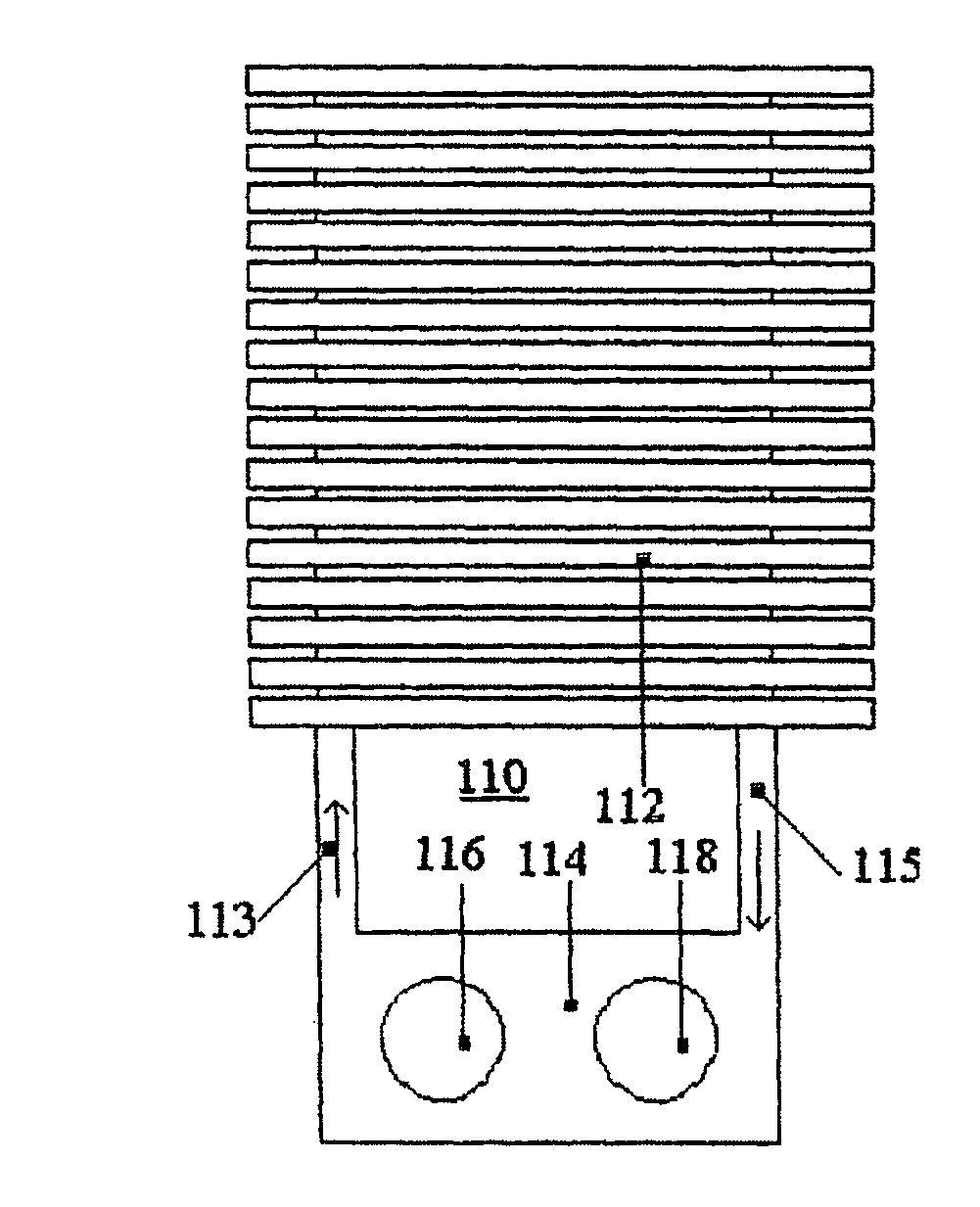
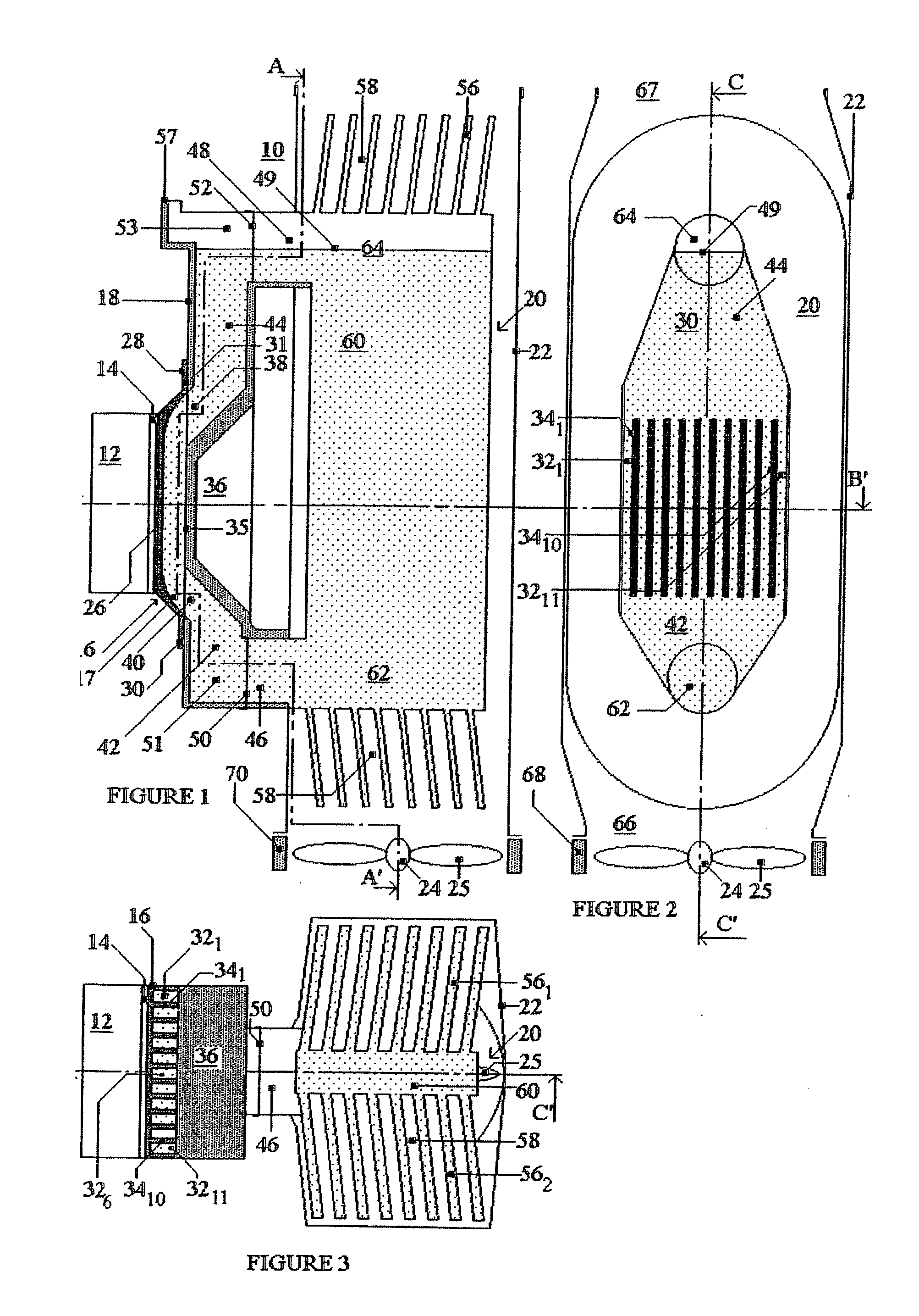
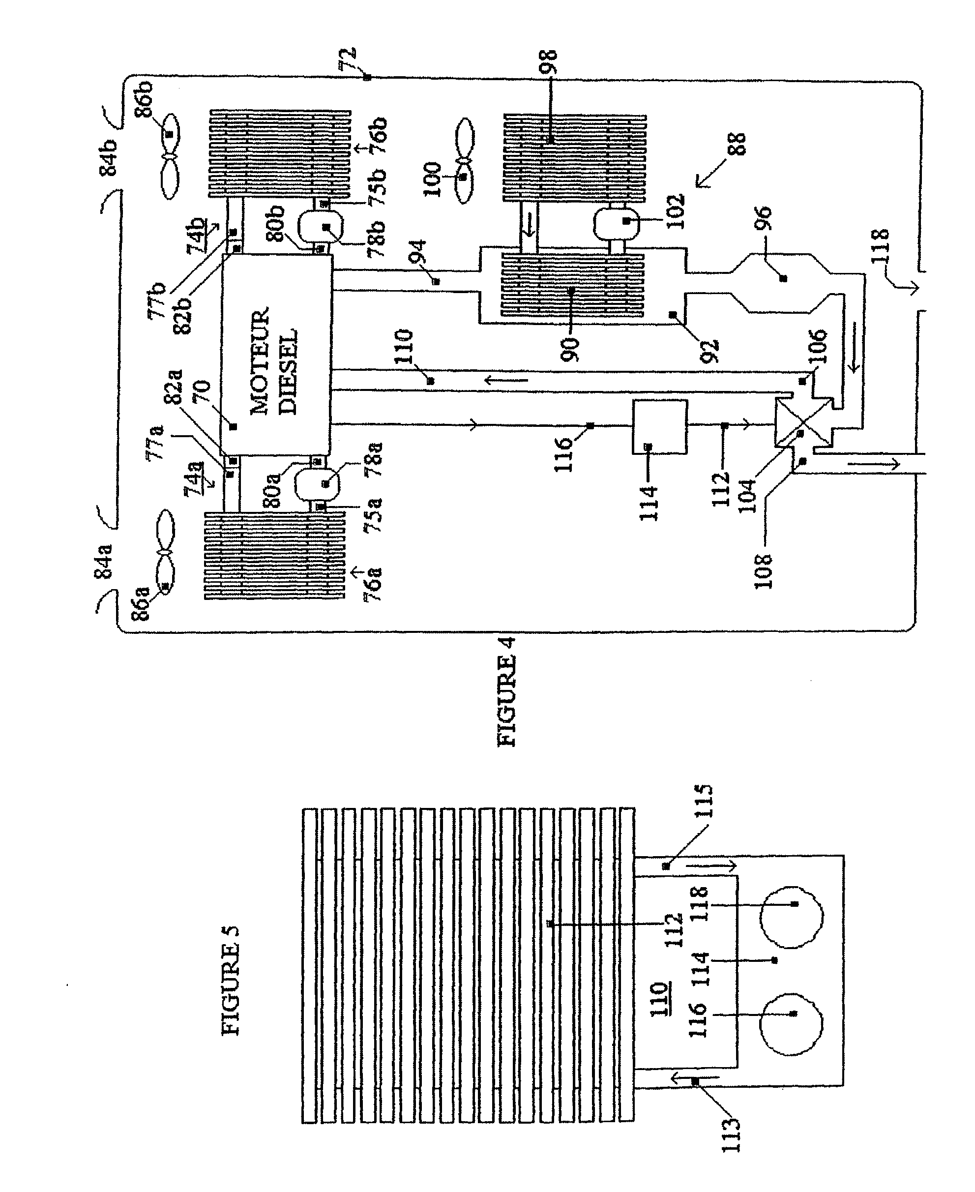
[0132] According to the first three figures, a cooling device 10, according to the invention, is installed vertically. It is coupled and fixed, by any appropriate means, to a microprocessor 12, capable of generating a thermal power of 120 Watts. This heat flow must be evacuated through a square precision-ground plate 14 for thermal dissipation, with sides of 35 mm (i.e. an average density of 10 W / cm2), so that its average temperature remains less than 70° C. for example. The cooler 10 comprises a mini-heater 16, a rigid hose 18, a radiator 20, a jacket 22 and a fan 24.

[0133] The mini-heater 16 is formed by a copper heating plate 17, applied to the hose 18. This heating plate 17 has a total thickness of 10 mm and it has an outer thermal coupling face 26, which is square and precision-ground and has 35 mm sides, connected by two inclines at its fixing edges 28-30, 10 mm wide, as well as a bottom 2 mm thick and side walls 1 mm thick. The internal face 31 of this heating plate 17 compr...


PUM

PropertyMeasurementUnit
thicknessaaaaaaaaaa
thicknessaaaaaaaaaa
thicknessaaaaaaaaaa

Abstract

The figure displays the diagram of a laminar flow water cooler (110) for a microprocessor comprising an integral radiator (112) provided with thin-walled and hollow fins which are produced by controlled compression of double convex bellows of a polymer or glass hot-blown blank. In order to form a closed circuit filled with water at the atmospheric pressure, the manifolds (113, 114, 115) of the radiator (112) are connected to the manifolds of an original component (114) formed by a mini heater (116) provided with a copper heating plate with internal grooved face and a mini pump (118) provided with a brushless electric motor devoid of a centrifugal turbine, wherein said mini heater and mini pump are disposed in a rigid small-sized moulded polymer hose. The total thermal resistance of said cooler can be equal to 0.15° / W that is of interest, in particular for high performance microprocessors for dissipating more than 200 W through the very hot central area of 1.5 cm2 of the heat dissipating surface thereof. The concept of the production of the inventive cooler makes it possible to design efficient and low-cost cooling devices which are usable for microprocessors, high-power electronic devices, thermal engines or fuel cells, in particular mounted in a motor vehicle. Said invention can be used for cooling any component dissipating a given thermal flux within the determined power and temperature limits.

Description

BACKGROUND OF THE INVENTION [0001] The invention relates to a major improvement to cooling devices which operate by heat exchange between a hot liquid and a cool fluid. Principally, the invention relates to coolers producing a water / air heat exchange and, secondly, to those in which the hot liquid is different to water and / or to those in which the cold fluid is different to air. [0002] Such cooling devices are associated with numerous components designed to dissipate a determined heat flow which, for each component concerned, depends both on the total power employed and on the yield obtained. Consequently, the heat flows relating to the coolers according to the invention are situated in two very wide ranges of powers and temperatures. By way of example, the range of these powers extends from substantially fifty Watts to substantially one hundred kilowatts. As regards the range of temperatures, its lower limit is at least a dozen degrees higher than the maximum temperature of the rea...

Claims


Application Information

Patent Timeline
Patent Type & Authority Applications(United States)
IPC IPC(8): H01M8/04F28F9/02
CPCF01P3/20F01P2005/125H01L2924/0002F01P2050/30F01P2060/02F02M25/0726F28D15/0266F28D2021/0031G06F1/20H01L23/427H01L23/473Y02T10/121F28F21/06H01L2924/00F02M26/22
Inventor DOMEN, JEAN-PAUL
Owner TECH DE LECHANGE THERMIQUE TET
Why Eureka
Try Eureka