Electrochemical device with alternative separator system

Active Publication Date: 2007-08-09
LG ENERGY SOLUTION LTD
View PDF3 Cites 65 Cited by
  • Summary
  • Abstract
  • Description
  • Claims
  • Application Information

AI Technical Summary

Benefits of technology

[0014] As a result of a variety of extensive and intensive studies and experiments to solve the problems as described above, the inventors of the present invention have discovered, as will be described hereinafter, the facts that, in fabrication of a stacked and folded electrochemical device comprising multi-stacked unit cells of full cells or bicells and a separation film which is interposed between stacked unit cells and is allowed to wrap each unit cell, when the separators inside the unit c

Problems solved by technology

However, when batteries are subjected to overcharging, heating or short-circuiting by internal or external factors, structural components of the batteries undergo abnormal chemical reactions, thereby resulting in increased internal temperature of the battery and generation of gases.
Gases thus generated lead to increased internal pressure of the secondary battery which further accelerates elevation of the battery temperature and gas generation, consequently causing explosion or ignition of the battery.
Safety elements disposed externally of the cell exert their functions by using changes of temperature, voltage or battery internal pressure and therefore ensure accurate shutdown, but suffer from disadvantages of high costs.
On the other hand, the methods of improving safety via incorporation of desired additive materials inside the cell have advantages of simple and convenient installation due to inclusion of the additive materials in the inside of the cell, but suffer

Method used


Image

  • Electrochemical device with alternative separator system
  • Electrochemical device with alternative separator system
  • Electrochemical device with alternative separator system

Examples


Example

Example 1

[0055] A separator interposed in a unit cell was fabricated by coating a ceramic material on a non-woven supporting material. The separator undergoes no thermal shrinkage until 150° C.

[0056] A cathode was fabricated by coating a slurry of a commonly known lithium cobalt oxide, PVDF and a conductive material on an aluminum current collector.

[0057] An anode was fabricated by coating a slurry of a commonly known graphite, PVDF and a conductive material on a copper current collector.

[0058] Then, the separator was interposed between the anode and cathode to fabricate a full cell.

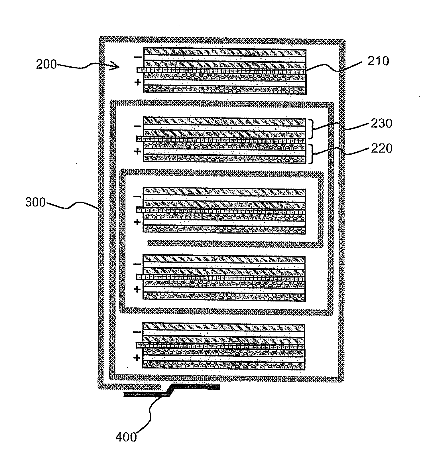
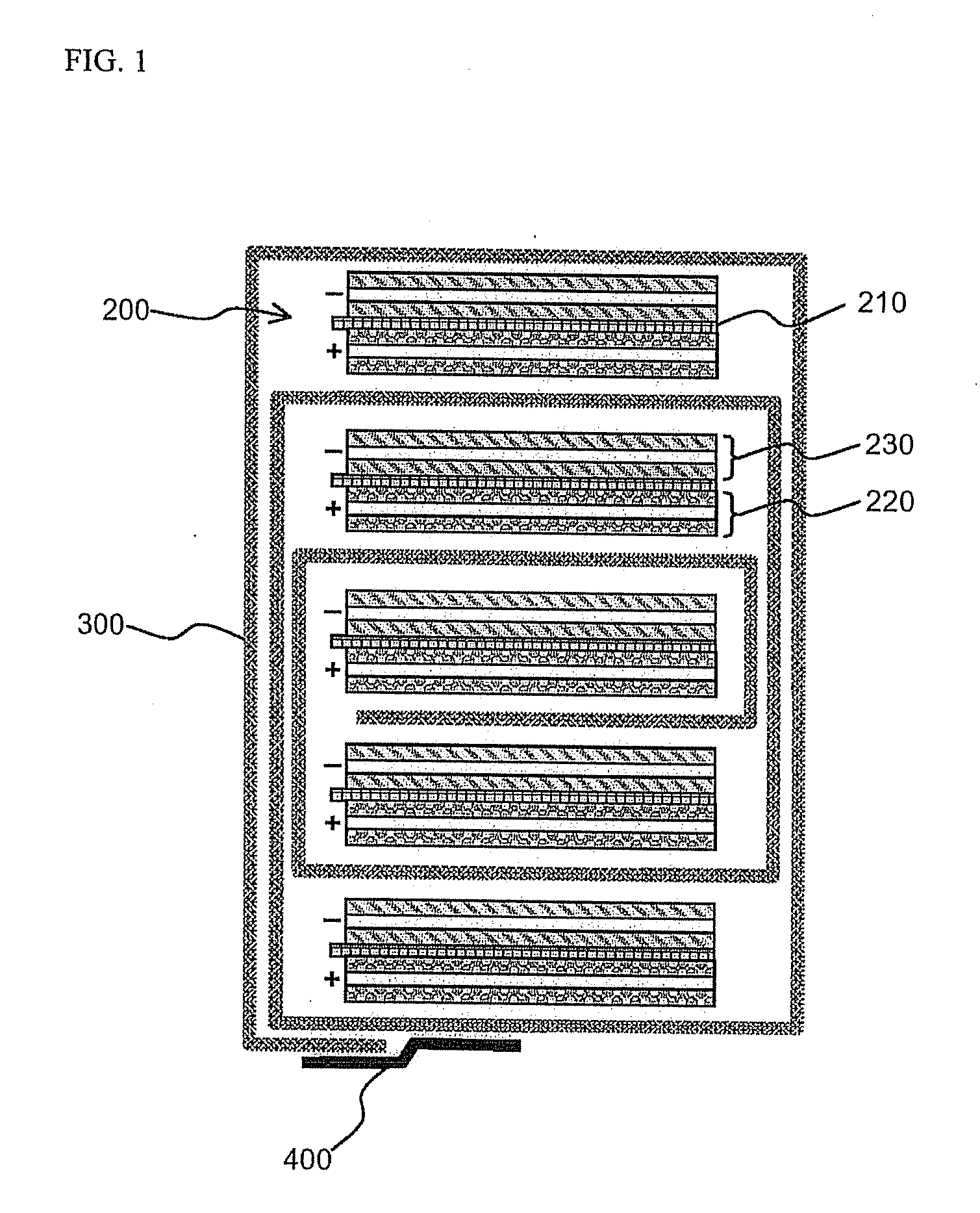
[0059] Using the full cells thus fabricated, an electrochemical device, as shown in FIG. 1, was fabricated with reference to the method disclosed in Korean Patent Laid-Open Publication No. 2001-82059. A polyethylene-based porous separation film was used as a separation film. This film can exert shutdown functions at 130° C.

Example

Comparative Example 1

[0060] A stacked and folded electrochemical device, as shown in FIG. 1, was fabricated in the same manner as in Example 1, except that a separator made of a material identical to that of a separation film was used.

Example

Experimental Example 1

[0061] Lithium ion secondary batteries were fabricated by injection of electrolytes into electrochemical devices of Example 1 and Comparative Example 1, followed by sealing.

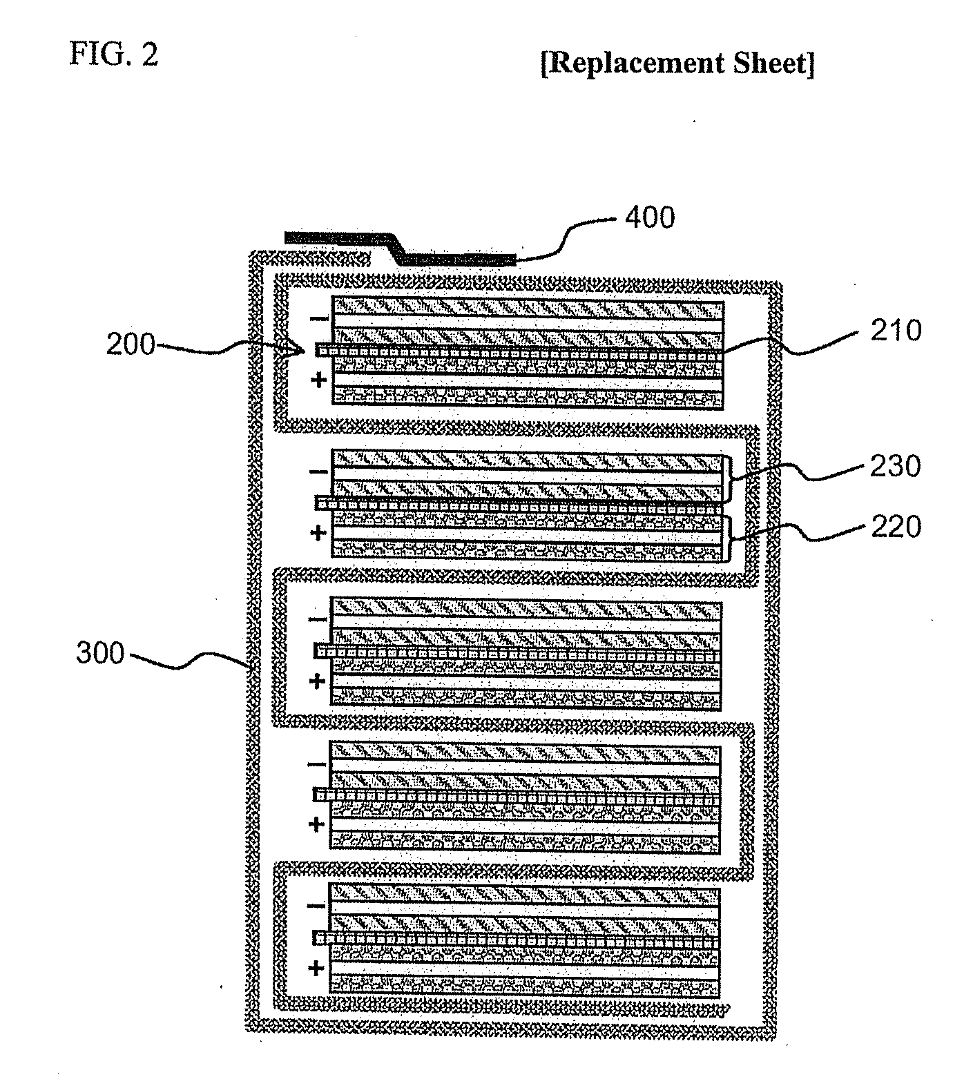
[0062] Upon performing overcharge and high-temperature exposure experiments for the batteries thus fabricated, it was confirmed that Example 1 using an alternately-stacked separator structure exhibits improved safety of the battery, as compared to Comparative Example 1.

INDUSTRIAL APPLICABILITY

[0063] As apparent from the above description, an electrochemical device according to the present invention can ensure thermal stability thereof, by stable induction of shutdown via thermal behavior of a separation film, without causing short-circuiting due to thermal shrinkage of a separator even when a temperature of a battery suddenly rises by internal or external factors.

[0064] Although the preferred embodiments of the present invention have been disclosed for illustrative purposes, those skill...


PUM


Abstract

Provided is an electrochemical device comprising multi-stacked unit cells of full cells or bicells and a separation film disposed therebetween, whereby the separation film and separators are alternately stacked between electrode layers with an opposite polarity. Herein, as the separation film is formed of a material having a higher thermal shrinkage rate than that of the separator, the thermal stability of the device can be secured by stable induction of shutdown via thermal behavior of the separation film, without causing short-circuiting due to thermal shrinkage of the separator even when a temperature of a battery suddenly rises by internal or external factors.

Description

FIELD OF THE INVENTION [0001] The present invention relates to an electrochemical device with an alternate separator system. More specifically, the present invention relates to an electrochemical device having improved stability via an alternately stacked structure of separator members at a regular interval, wherein the separator members exhibit different thermal behavior due to difference of a thermal shrinkage rate between separators of unit cells and a separation film which is disposed between unit cells. BACKGROUND OF THE INVENTION [0002] In recent years, as a great deal of interest has been increasingly directed to energy storage technology, efforts and attempts to research and develop batteries capable of implementing such technology have been increasingly undertaken. In this respect, the field of electrochemical devices has been receiving a great deal of attention, and in particular, a lot of interest has been focused on the development of rechargeable secondary batteries. [0...

Claims


Application Information

Patent Timeline
IPC IPC(8): H01M2/16H01M6/46H01M2/02H01M50/414H01M50/434H01M50/463
CPCH01M2/1646H01M2/1653Y02E60/122H01M10/0525H01M2/18Y02E60/10H01M50/463Y02P70/50H01M50/414H01M50/434H01M50/20H01M50/40
Inventor KIM, JE YOUNGPARK, PIL KYUAHN, SOONHO
Owner LG ENERGY SOLUTION LTD
Why Eureka
Try Eureka