Rotary Mower Blade Sharpener Having Movable Griding Wheels

a technology of rotary mower blades and griding wheels, which is applied in the direction of grinding machine components, other manufacturing equipment/tools, manufacturing tools, etc., can solve the problems of slow sharpener throughput and slow sharpener throughpu

Active Publication Date: 2007-08-09
FOLEY BELSAW
View PDF35 Cites 36 Cited by
  • Summary
  • Abstract
  • Description
  • Claims
  • Application Information

AI Technical Summary

Benefits of technology

[0007]The present invention provides an improved mower blade sharpening apparatus and method in which a blade to be sharpened is positioned in a fixed state, and one or more movable grinding wheels are provided. When two grinding wheels are provided, each of the grinding wheels moves along one of the two cutting edges of the blade to be sharpened, and preferably both wheels move simultaneously toward the cente

Problems solved by technology

Those adjustments slow sharpener throughput when large numbers of blades need sharpening.
Also, once the grinding has been performed, the blade

Method used


Image

  • Rotary Mower Blade Sharpener Having Movable Griding Wheels
  • Rotary Mower Blade Sharpener Having Movable Griding Wheels
  • Rotary Mower Blade Sharpener Having Movable Griding Wheels

Examples


Embodiment Construction

[0018]The sharpener will now be described in further detail with reference to the accompanying drawings.

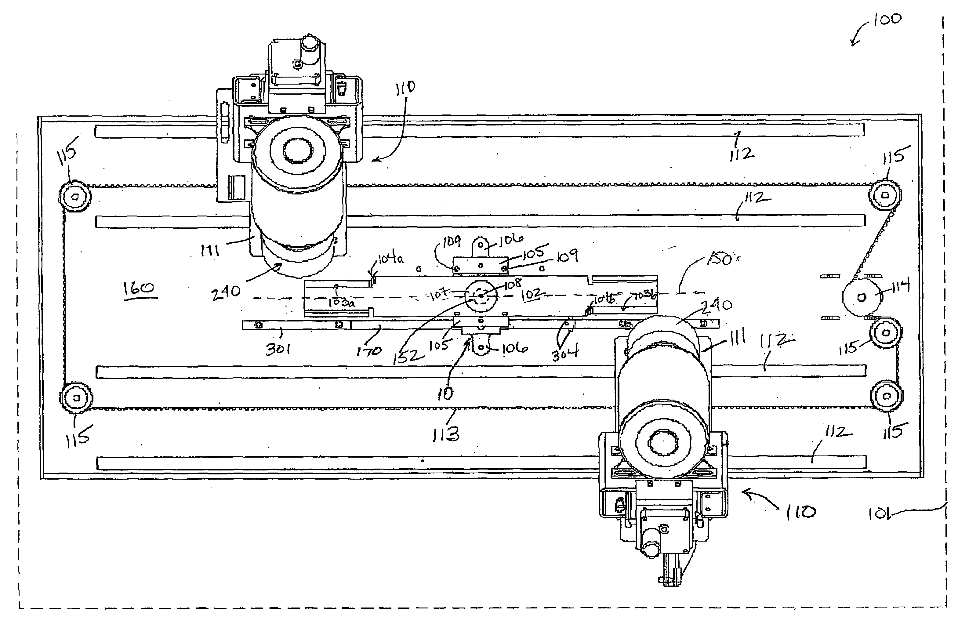
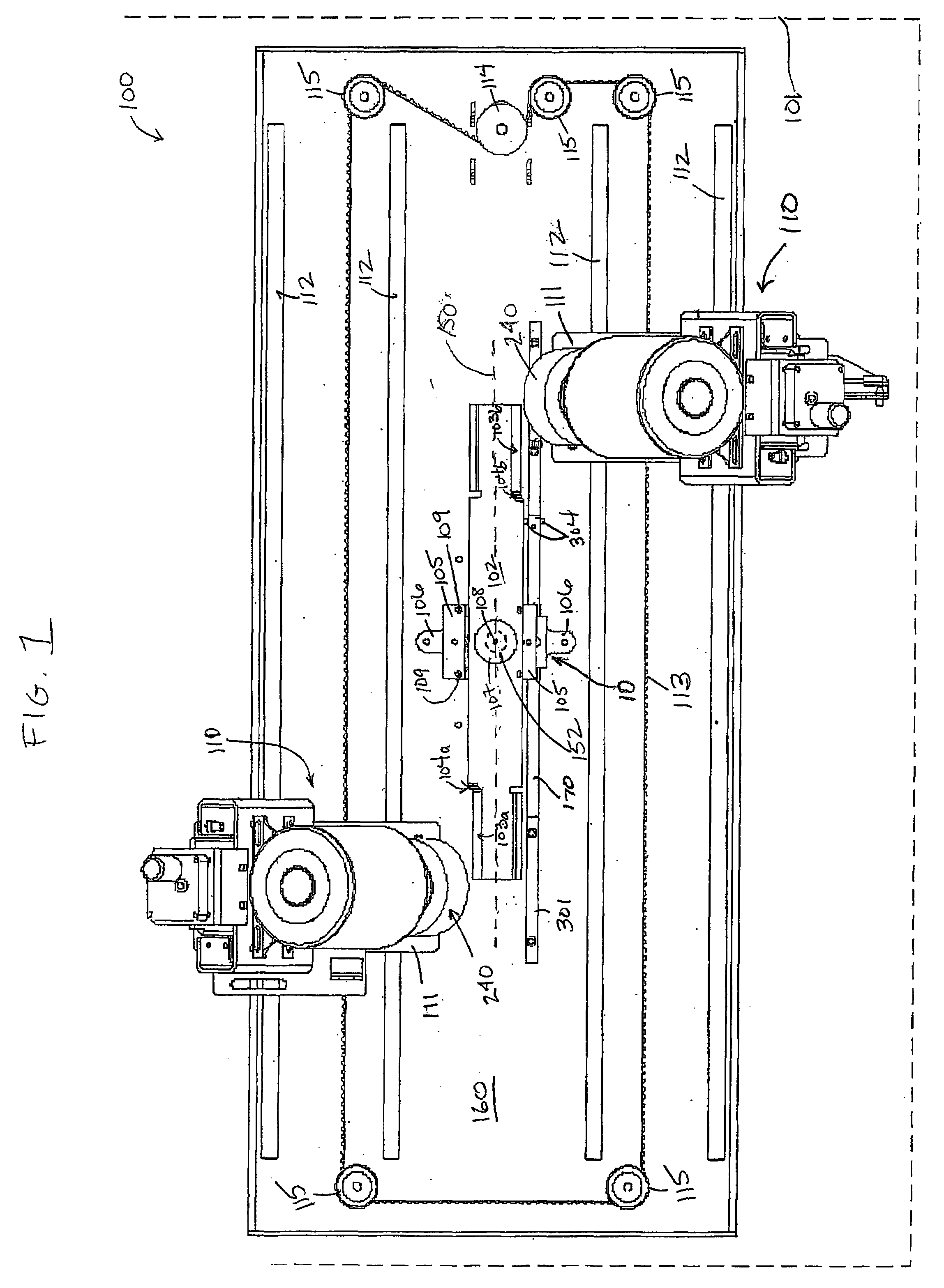
[0019]Overall Assembly. FIG. 1 provides a diagram of a sharpening device 100 in accordance with one embodiment of the present design. A mower or other rotary blade 102 to be sharpened has substantially straight cutting edges 103a, 103b on opposite ends and opposed sides of the blade 102. Straight cutting edges 103a, 103b may be substantially parallel with the longitudinal axis 150 of blade 102 or may be angled in relation to the longitudinal axis of blade 102. Cutting edges 103a, 103b may have an innermost portion 104a, 104b that is a curved, strain relief portion of the blade 102 that is desirable to reduce stress on the cutting edges when used in mowing or other cutting operations. The blade 102 is positioned in the sharpening device 100, which may be enclosed by a cabinet (indicated at 101) with a generally vertical main base 160. The blade 102 is attached to the sharpening dev...


PUM

PropertyMeasurementUnit
Angleaaaaaaaaaa

Abstract

A device and method for sharpening a mower blade are provided, in which a mounting device for mounting a rotary blade having two opposite cutting edges to be sharpened, wherein the mounting device is capable of positioning the blade in a first fixed state and a second, axially pivoting state. One or more grinding head assemblies are each positioned on an opposite end of the blade, wherein the grinding head assemblies respectively grind the two opposite cutting edges to be sharpened. A control system controls movement of the two grinding head assemblies. The mounting device positions the blade in the first fixed state to enable the two grinding head assemblies to grind the cutting edges in a direction substantially parallel to the cutting edges of the blade to perform a straight grind, and then may position the blade in the second axially pivoting state to enable the blade to pivot around its blade rotation axis away from the grinding head assemblies upon completion of the straight grind, thereby forming a curve at the end of each cutting edge. The mounting assembly also holds the blade in a third, freely rotating state in which the blade may substantially freely rotate around its blade rotation axis to enable balancing of the blade after sharpening.

Description

RELATED APPLICATIONS[0001]This application claims priority to U.S. Provisional Application Ser. No. 60 / 771,242, filed Feb. 8, 2006, entitled “Rotary Mower Blade Sharpener Having Movable Grinding Wheels,” which is incorporated herein by reference in its entirety.BACKGROUND OF THE INVENTION[0002]Rotary mowers operate by having a generally planar blade that rotates around its midpoint (a blade rotation axis perpendicular to the blade plane) in a plane substantially parallel to the ground over which the mower runs. The blade typically has two cutting edges, one on each of opposed sides of the blade's longitudinal axis. One cutting edge extends from one distal end of the blade toward the midpoint of the blade along one edge of the blade, and the other cutting edge extends from the opposite distal end of the blade toward the midpoint of the blade along the opposite edge of the blade from the first cutting edge. The cutting edges must be sharpened periodically to provide desired mowing cap...

Claims


Application Information

Patent Timeline
IPC IPC(8): B24B51/00B24B1/00
CPCB24B3/365B24B41/06B24B27/0076
Inventor DIECK, JAMES H.VEENENDALL, GREGORY A.
Owner FOLEY BELSAW
Why Eureka
Try Eureka