Laparoscopic Laser Device and Method

a laser device and laser technology, applied in the field of tissue laser treatment, can solve the problems of affecting the actual vaporization of tissue, affecting the physician's ability to see what is actually happening at the target tissue, and interfere with the radiation being applied to the target tissue, so as to reduce the amount of laser light energy absorbed by the irrigating liquid, reduce and achieve the effect of reducing the heating of the irrigating liquid

Inactive Publication Date: 2007-08-09
AMS RES CORP
View PDF28 Cites 252 Cited by
  • Summary
  • Abstract
  • Description
  • Claims
  • Application Information

AI Technical Summary

Benefits of technology

[0007]A drawback associated with using lasers in laparoscopic surgery is that the vapor, mist, gases and smoke, hereinafter commonly collectively referred to as smoke, typically produced by the laser light acting upon the target tissue can make it very difficult for the physician to see what is actually happening at the target tissue, and interfere with the radiation being applied for vaporization of the tissue. The smoke can prevent the physician from properly vaporizing the target tissue. One of the primary aspects of the invention is the recognition that if one were to irrigate the target tissue, such as along the laser light path from the tip of the instrument to the target tissue, the irrigating liquid would capture the smoke and aid visualization of the target site. By the appropriate choice of the irrigating liquid and / or the wavelength of the laser light, the amount of the laser light energy absorbed by the irrigating liquid can be substantially reduced or effectively eliminated. This provides the dual advantages of allowing more energy to reach the target tissue and reducing heating of the irrigating liquid. The latter is important because the irrigating liquid can help cool the surrounding tissue to protect the surrounding tissue from preventable damage. Also, substantially reducing or effectively eliminating the absorption of laser light energy by the irrigating liquid helps to prevent the irrigating liquid from vaporizing, which would itself interfere with the view of the target tissue and the ability of the irrigating liquid to effectively suppress any smoke created by the laser light acting on the target tissue.
[0008]It has been recognized that as more and more laser energy is consumed by vaporization of the tissue, the amount of laser energy leading to residual tissue coagulation gets smaller, i.e. the amount of residual coagulation drops, and the side effects attendant to the residual injury caused by the surgery drop dramatically. Thus, the extent of the zone of thermal damage characterized by tissue coagulation left after the procedure gets smaller with increasing volumetric power density, while the rate of vaporization increases. Substantial and surprising improvement in results is achieved. It has been recognized that increasing the volumetric power density absorbed in the tissue to be ablated has the result of decreasing the extent of residual injury of the surrounding tissue. This recognition leads to the use of higher power laser systems, with greater levels of irradiance at the treatment area on the tissue, while achieving the lower levels of adverse side effects and a quicker operation times.

Problems solved by technology

A drawback associated with using lasers in laparoscopic surgery is that the vapor, mist, gases and smoke, hereinafter commonly collectively referred to as smoke, typically produced by the laser light acting upon the target tissue can make it very difficult for the physician to see what is actually happening at the target tissue, and interfere with the radiation being applied for vaporization of the tissue.

Method used


Image

  • Laparoscopic Laser Device and Method
  • Laparoscopic Laser Device and Method
  • Laparoscopic Laser Device and Method

Examples


Embodiment Construction

[0030]The following description of the invention will typically be with reference to specific structural embodiments and methods. It is to be understood that there is no intention to limit the invention to the specifically disclosed embodiments and methods but that the invention may be practiced using other features, elements, methods and embodiments.

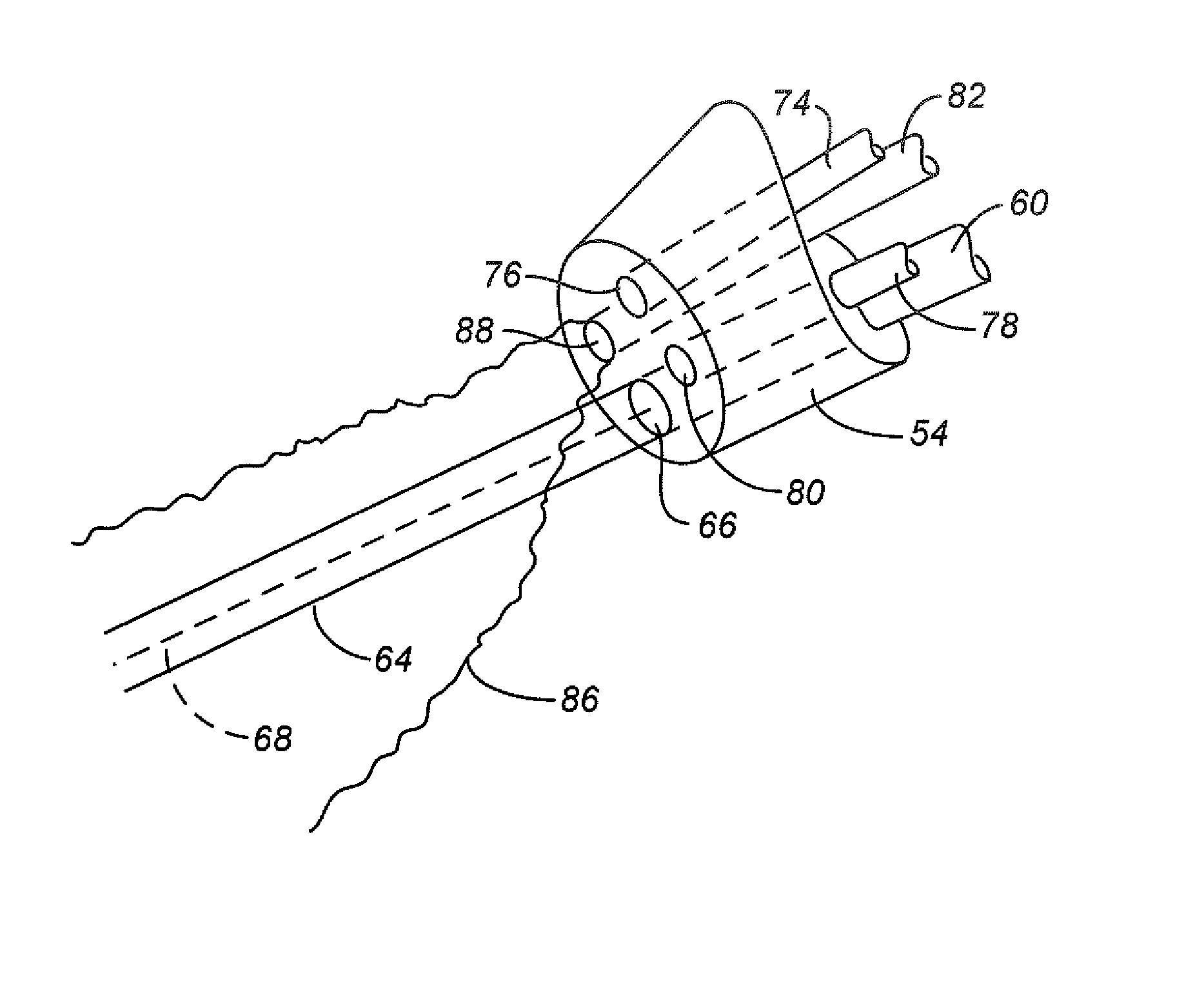
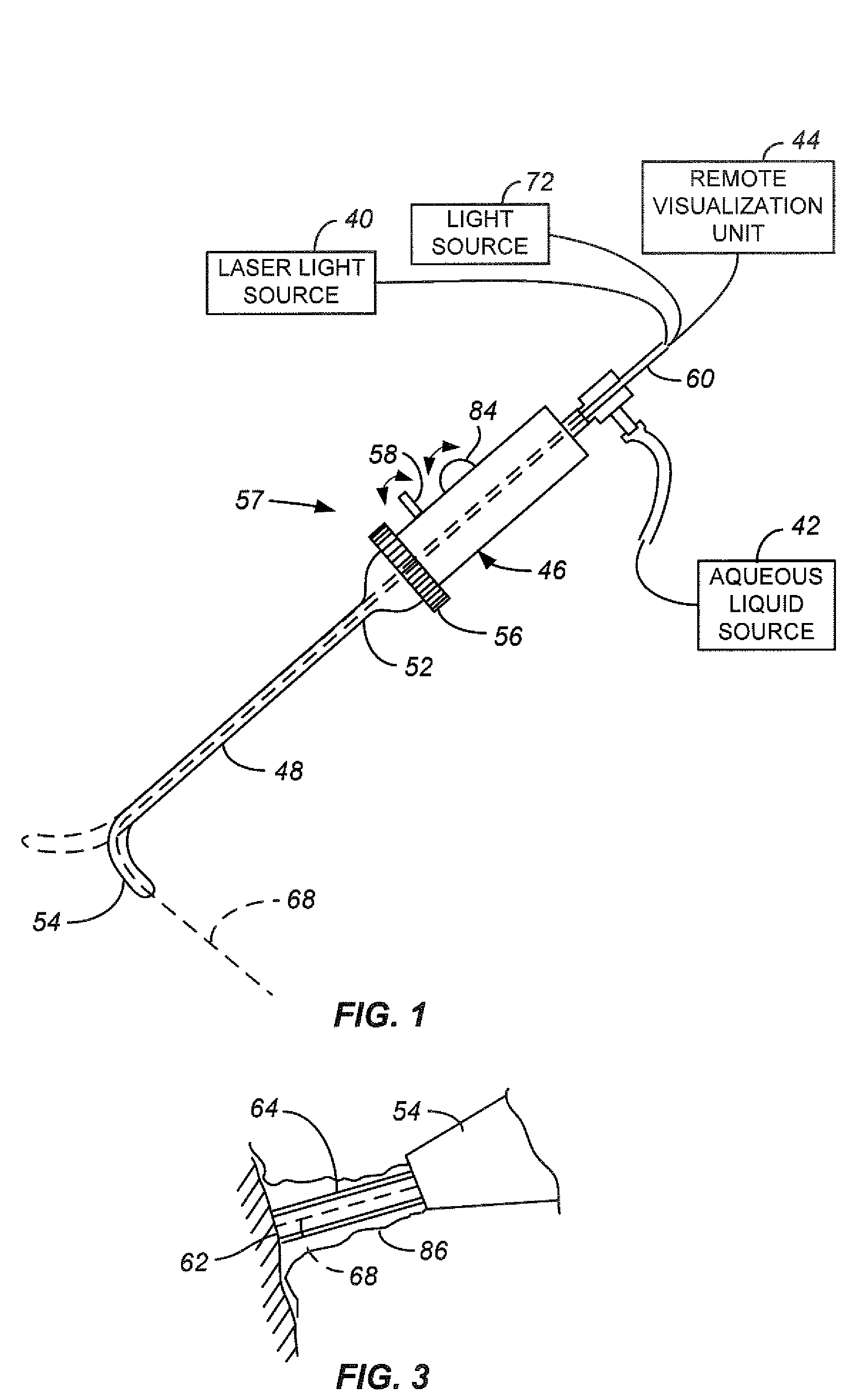
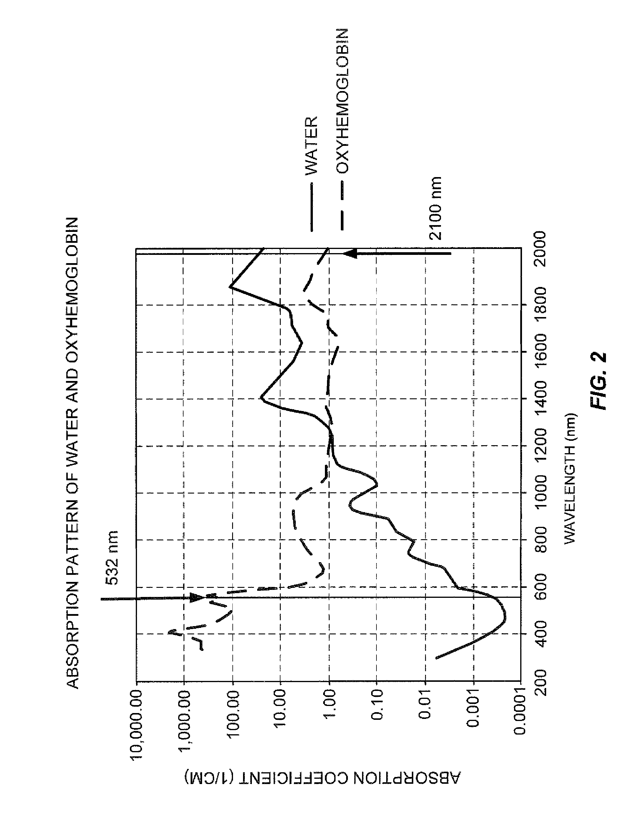
[0031]FIG. 1 illustrates a laparoscopic laser system 36 including a laparoscopic laser device 38 coupled to a laser energy source 40, an aqueous liquid source 42 and a remote visualization unit 44. The laser energy source is chosen so that the laser energy is only minimally absorbed by the irrigating liquid used, typically an aqueous liquid. FIG. 2 is a graph illustrating the absorption pattern of water and oxyhemoglobin. The absorption coefficient of water for laser wavelengths of 400-600 nm is extremely low, with the absorption coefficient of lasers having a wavelength of 532 nm being plotted on the graph. At the same time laser wavel...


PUM


Abstract

Laser radiation delivered to a treatment area causes vaporization of a substantially greater volume of tissue than the volume of residual coagulated tissue. The laser radiation may have a wavelength of about 300 nm to about 700 nm, may be used with a smoke suppressing irrigant, may have an average irradiance greater than about 5 kilowatts / cm2, and may have a spot size of at least 0.05 mm2. A laparoscopic laser device, for use with an insufflated bodily cavity, may include an elongate body adapted for insertion into an insufflated bodily cavity. A laser energy delivery element, at the distal end of the elongate body, may be coupleable to a source of tissue-vaporization-capable laser energy and capable of delivering laser energy along a laser energy path extending away from the laser energy delivery element. A smoke-suppressing liquid pathway, extending along the elongate body to an exit opening at the distal end, may be coupleable to a source of a smoke-suppressing liquid. The smoke-suppressing liquid is directed generally along the laser energy path. A remote visualization device may be used to view along the laser energy path.

Description

RELATED APPLICATION INFORMATION[0001]The present application claims the benefit of provisional Patent Application No. 60 / 765,879, filed 7 Feb. 2006. The present application is related to the following: U.S. patent application Ser. No. 10 / 371,080 filed 21 Feb. 2003; U.S. Pat. No. 6,986,764, issued 17 Jan. 2006; U.S. Pat. No. 6,554,824 issued 29 Apr. 2003; and U.S. patent application Ser. No. 10 / 279,087, filed 23 Oct. 2002.BACKGROUND OF THE INVENTION[0002]1. Field of the Invention[0003]The present invention relates generally to laser treatment of tissue, and more particularly to the laparoscopic resection, vaporization and coagulation of tissue, such as prostate, kidney and liver tissue, in a hemostatic and photoselective fashion.[0004]2. Description of Related Art[0005]A commonly employed procedure for removal of tissue in the treatment of various medical conditions involves the use of a laparoscopic laser device. Laparoscopic surgery typically involves insufflating the bodily cavity...

Claims


Application Information

Patent Timeline
Patent Type & Authority Applications(United States)
IPC IPC(8): A61B18/18
CPCA61B18/24H01S3/1643A61B2018/00982A61B2019/5206A61B2218/008H01S3/0612H01S3/08045H01S3/08072H01S3/0817H01S3/09408H01S3/09415H01S3/1022H01S3/109H01S3/11H01S3/1611A61B2017/003A61B2090/306H01S3/1123
Inventor NAHEN, KESTER
Owner AMS RES CORP
Why Eureka
Try Eureka