Fuel storage system for a vehicle

a fuel storage system and vehicle technology, applied in the direction of transportation and packaging, functional valve types, containers, etc., can solve the problems of inconvenient maintenance, inconvenient maintenance, and inability to meet the needs of vehicles, so as to improve the pressure control of the fuel tank, reduce hydrocarbon emission into the environment, and improve the flexibility of vehicle fuel tanks

Inactive Publication Date: 2007-08-16
TI GRP AUTOMOTIVE SYST LLC
View PDF11 Cites 9 Cited by
  • Summary
  • Abstract
  • Description
  • Claims
  • Application Information

AI Technical Summary

Benefits of technology

[0009] A fuel storage system for a passenger, transportation or recreational vehicle has an on-board fuel tank that carries a self-referencing vapor assembly for seeking out vapor pockets and controllably removing fuel vapor from the tank. Preferably, a vent manifold attaches to a flange that sealably covers an access hole of the tank. At least one flexible vapor line extends from the manifold in the tank to a vapor vent valve that floats upon the surface of fuel. When floating upon the fuel surface, the vapor vent valve is open to communicate the vapor dome through the vapor line and preferably with a carbon canister for hydrocarbon storage. As fuel surface levels change or the vehicle tilts, changing the vapor dome size or location in the tank, the floating vapor vent valve is sufficiently free to move generally with the vapor dome and as permitted by the flexibility of the vapor line. In tank orientations where the vapor vent valve falls below the surface of fuel,

Problems solved by technology

Such a backup could cause the automatic shut-off fuel pump nozzle to prematurely shut-off before maximum fuel level is reached.
Unfortunately, if the tank has two vapor domes or two high elevation points, known fuel storage systems having only one fixed vent valve can vent only one of the vapor domes.
Because the vapor in the other vapor dome can not be displaced with fuel, the storage capacity of the tank is undesirably limited.
Moreover, if the vehicle is traveling down or up a steep embankment, the tank is no longer generally horizontal and a substantially full tank of fuel could submerge the float of the fixed vent valve thus closing the vent valve while the engine is operating.
With the vent valve closed and the engine consuming fuel or with the fuel being heated by a return l

Method used


Image

  • Fuel storage system for a vehicle
  • Fuel storage system for a vehicle
  • Fuel storage system for a vehicle

Examples


Embodiment Construction

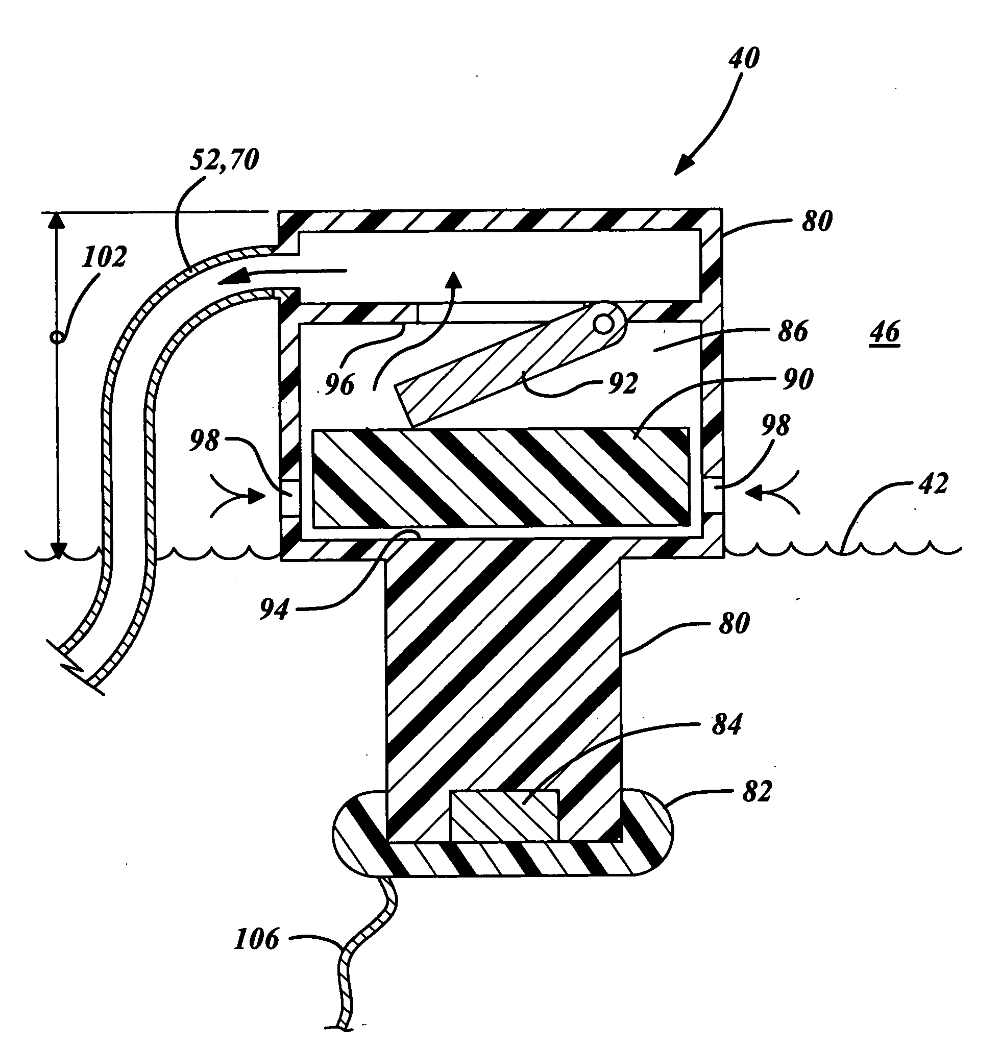
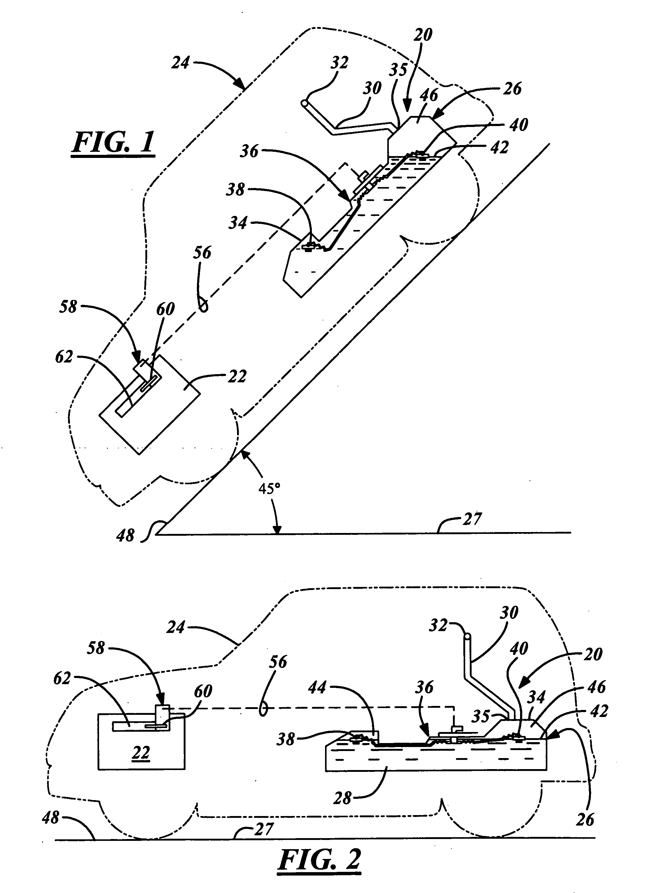
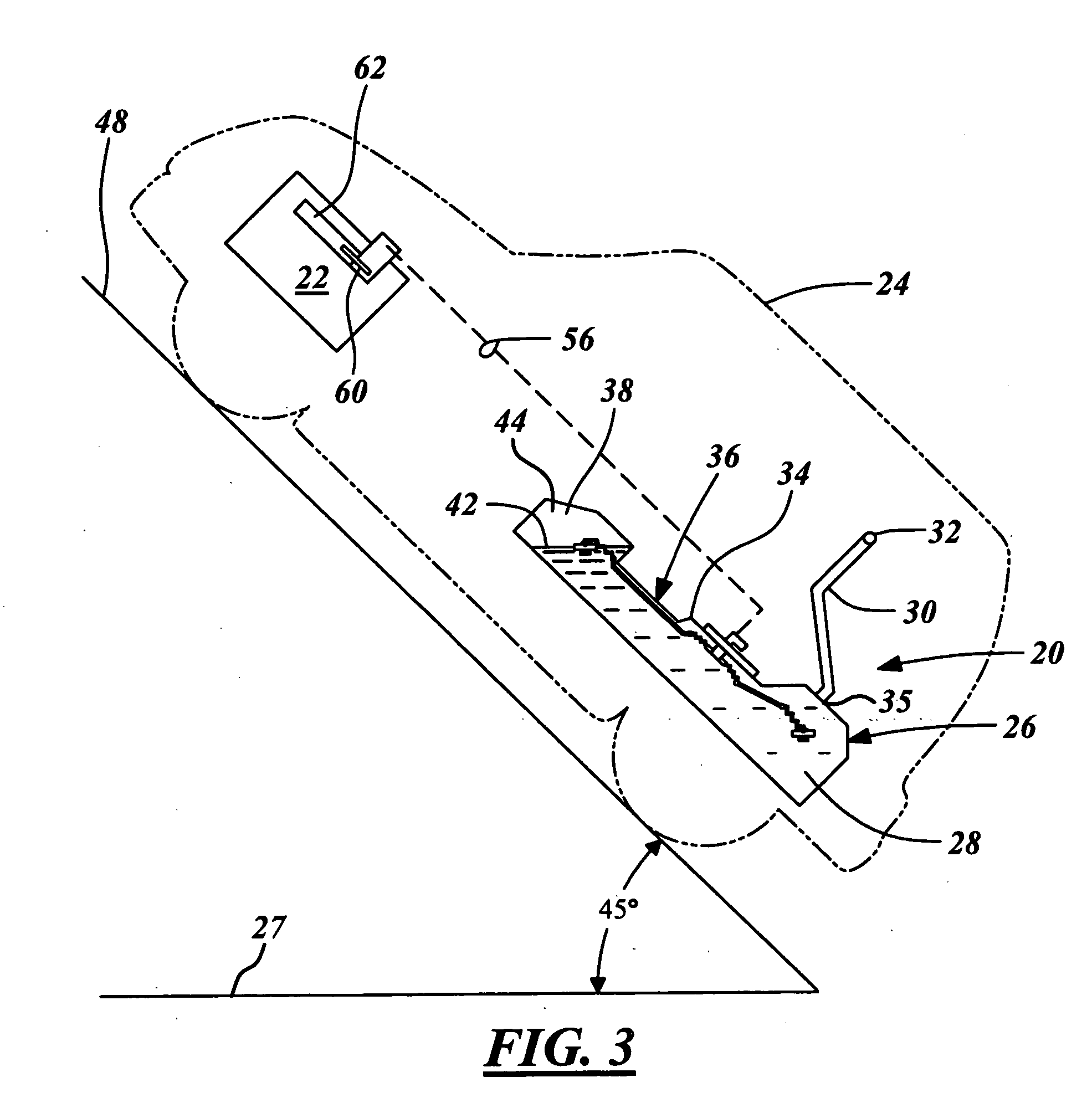
[0020] As best illustrated in FIGS. 1-5, a fuel storage system 20 according to one embodiment of the present invention generally stores on-board fuel for use in a combustion engine 22 of a vehicle 24. During normal refueling operations of the vehicle 24 when typically at a refueling station, a remote fuel pump having an automatic shut-off fuel pump nozzle is designed to quickly and conveniently refuel a tank 26 of the fuel storage system 20. When refueling at the station, government regulatory requirements dictate that an incline 48 of the vehicle 24, and thus generally the on-board fuel tank 26, falls within an approximate angular range of plus and minus three degrees with reference to an imaginary horizontal plane 27 (herein referred to as on-road refueling and best illustrated in FIG. 2). When refueling the tank 26 within this angular range, the fuel storage system 20 must receive the supply fuel at a predetermined high volumetric flow rate through a fill tube 30 without creating...


PUM


Abstract

A fuel storage system for a transportation or recreational vehicle has a fuel tank that carries a vapor assembly that seeks out vapor pockets and controllably removes fuel vapor from the tank without releasing hydrocarbons to the surrounding environment. Preferably, a vent manifold attaches to a flange that sealably covers an access hole of the tank. At least one flexible tentacle extends from the manifold in the tank to a respective vapor vent valve that floats upon the surface of fuel at a vapor dome. When freely floating, the vent valve is open thus communicates the vapor dome through the tentacle and preferably with a filtering carbon canister. As fuel surface levels change or the vehicle tilts, changing the vapor dome size or location in the tank, the floating vapor vent valve is free to move generally with the vapor dome and as permitted by the flexibility of the trailing tentacle. With tank orientations where the vapor vent valve falls below the surface of fuel, the vent valve automatically closes to prevent flooding of the respective tentacle and remote vapor canister.

Description

FIELD OF THE INVENTION [0001] The present invention relates to a fuel storage system for a vehicle and more particularly to a fuel level vapor assembly of the fuel storage system. BACKGROUND OF THE INVENTION [0002] Environmental concerns and governmental regulations require reduced emissions of volatile hydrocarbon fuel vapors into the atmosphere. One source of hydrocarbon fuel vapors is the fuel tanks of vehicles using gasoline or other hydrocarbon fuels with high volatility. Fuel vapor can escape to the atmosphere during the filling of the tanks and usually even after the tanks are filled. [0003] The use of an onboard vapor recovery system to remove excess fuel vapor from the fuel tank is one solution to the problem. Typically, a canister with activated charcoal therein receives fuel vapors through a vent valve mounted in the top of the fuel tank or within a flange of an in-tank fuel pump module for communication with a vapor dome in the tank. The vent valve is usually responsive ...

Claims


Application Information

Patent Timeline
IPC IPC(8): F16K24/04
CPCB60K15/035B60K2015/0772B60K2015/03533B60K15/03504Y10T137/3099Y10T137/86252B60K15/03B60K15/06
Inventor HILDERLEY, STEVEN R.OSBORNE, JAMES R.
Owner TI GRP AUTOMOTIVE SYST LLC
Why Eureka
Try Eureka