Device and method for stiffening a web destined to be wound in logs

Inactive Publication Date: 2007-08-16
PAPER CONVERTING MASCH CO INC
View PDF8 Cites 5 Cited by
  • Summary
  • Abstract
  • Description
  • Claims
  • Application Information

AI Technical Summary

Benefits of technology

[0022] An object of the present invention is to overcome the drawbacks of the prior art by providing a device and a method for stiffening of a web destined to be wound into logs, that are able to ensure correct winding of the log, reducing production times and avoiding the use of additional devices which lead to greater complexity of management and higher costs.
[0025] The stiffening device according to the invention is able to create on the web at least one longitudinal strip with greater stiffness, and is destined to be placed upstream of a winding unit so as to obtain in the log formed in the winding unit at least one sector with a greater stiffness to avoid deformation of the log during winding.
[0026] The method provides for the creation of sectors of the log, generally two at the outer ends of said log, with a greater density. In this manner the pressure exerted on the log by the winding rollers is sustained by these sectors with a greater stiffness, reducing deformation of the log. A winding condition similar to that obtained in the production of products with a standard density is thus created.
[0029] This system of stiffening of longitudinal strips of the web provides advantages not only for winding of the log but also for improving management of the paper tension during processing of webs of soft paper with a greater volume of sheet products obtained by means of a particular process called TAD (Through Air Dried). In fact the drawing pressure roller unit (a pair of rollers, one of which is high-grip to tension the paper web downstream of the folding unit) exerts a higher pressure on the strips of web with a greater thickness, obtaining greater control of the web. This condition leads to an advantage, also considering that during processing of some of the aforementioned products excessive generalized pressure on the whole width of the web would cause mechanical stress and a reduction in the volume of the paper which would be unacceptable for the purposes of the quality of the product.
[0030] It should be noted that the stage of creating portions of web with a greater thickness and density can be generated upstream of the rewinding machine, by creating a unit / machine specially dedicated to this operation. Alternatively, it is possible to install the stiffening device in the rewinding machine upstream of the drawing pressure rollers, to exploit the better paper tension managing capability, and in any case before the winding unit.

Problems solved by technology

This winding system shows some limits when soft logs with a reduced paper density are being produced.
Production of this type of products, with product quality complying with the manufacturer's specifications, is possible only by reducing the winding speed, with a consequent reduction in the productivity of the machine.
In fact, during winding, the winding rollers, at the point of contact with the log, do not encounter sufficient resistance to compression and deform the rotating log which becomes strongly unbalanced.
Extraction of the log obtained by creating a sudden difference in peripheral speed between the winding rollers is less effective with soft logs, because of the smaller contrast pressure that can be exerted by the rollers.
There are also drawbacks in gluing of the end edge of the log in the gluing machine situated downstream of the rewinding machine.
This gluing system is less effective with soft logs because of the smaller contrast pressure that can be exerted by the preceding rollers on the log.
The above described manufacturing defects mean that the product does not comply with the required quality specifications and performance of the machine is limited because of the reduction in speed and the difficulties in managing the discharge and edge gluing stage.
FIG. 8 shows shift and circularity errors in the production of “soft” logs.
However, this method and device present some drawbacks.
Such a device is complex because it must allow management of the movements of extraction and return of the chucks, the movement to follow the trajectory of the core during the introduction stage, and the movement to follow the trajectory of the axis of the log during formation, due to the increase in diameter of said log.
In order to prevent the time for return of the chucks to the core catching position at the end of winding from increasing the introduction times, it is necessary to have a second pair of chucks, with a further increase in the complexity of the device and the relative costs.

Method used


Image

  • Device and method for stiffening a web destined to be wound in logs
  • Device and method for stiffening a web destined to be wound in logs
  • Device and method for stiffening a web destined to be wound in logs

Examples


Embodiment Construction

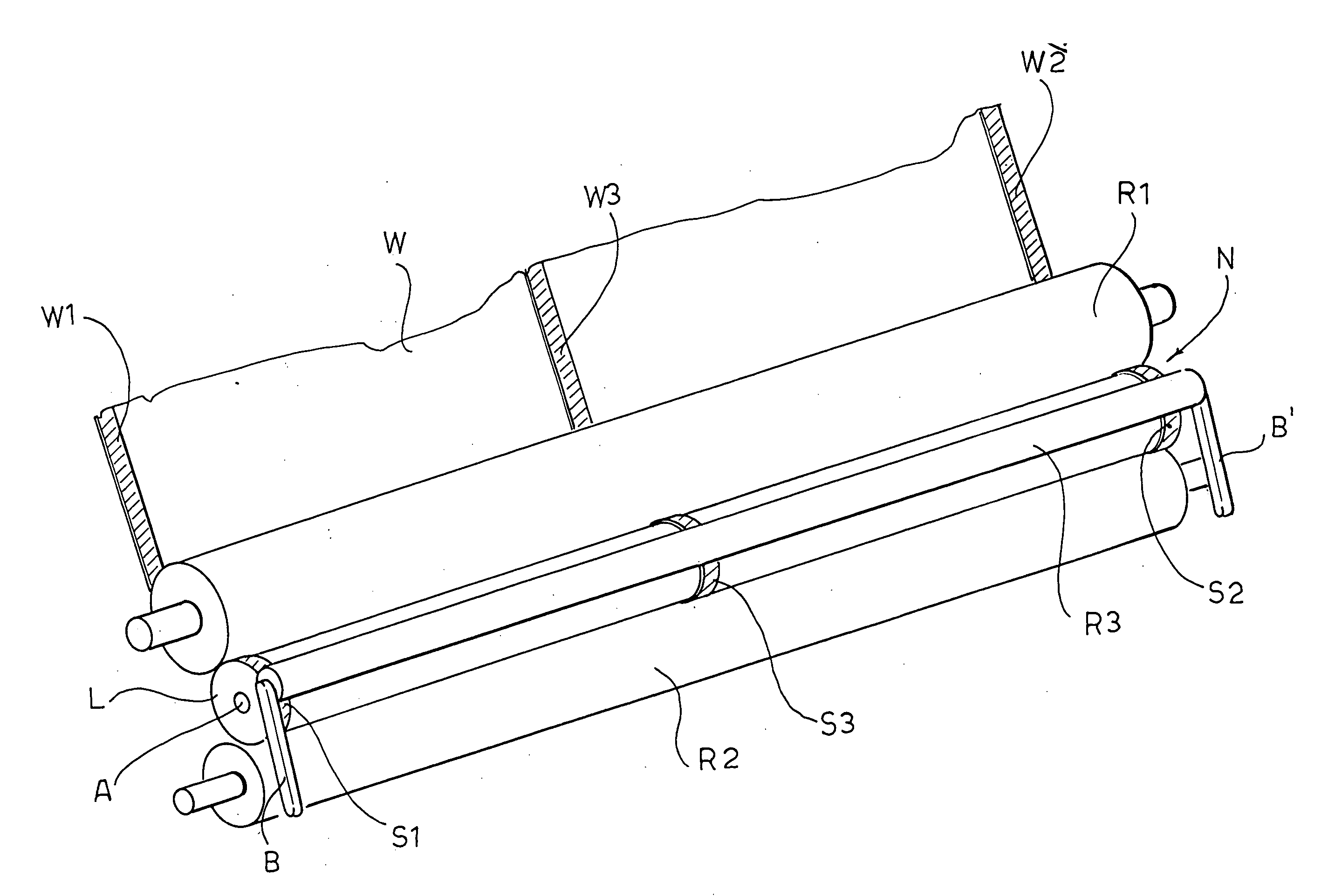
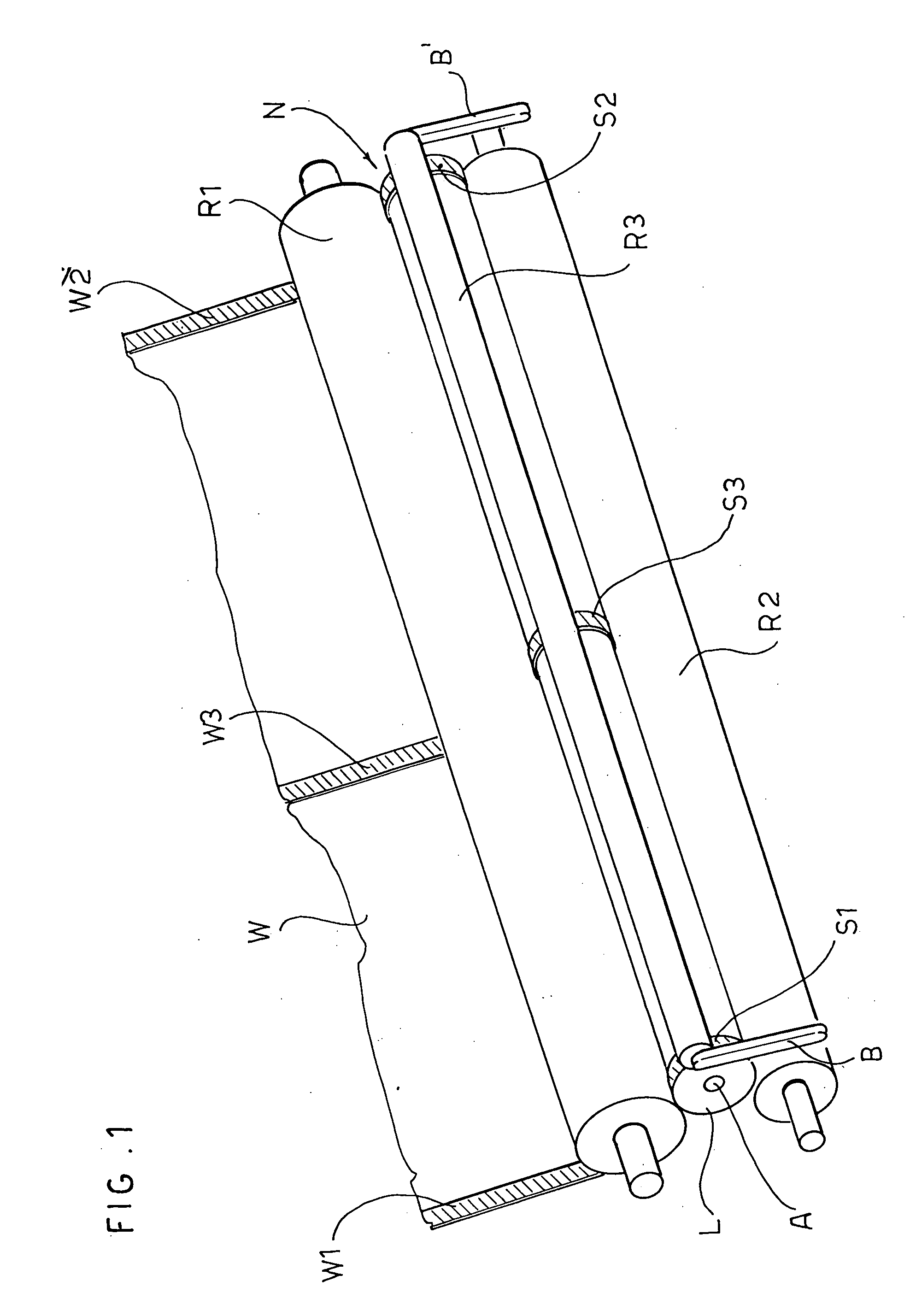
[0043]FIG. 1 shows a winding cradle N of a rewinding machine. The rewinding cradle N is a gap created between a set of 3 rollers: a first winding roller R1, a second winding roller R2 and a movable roller R3, commonly known as a pressure roller. In the winding cradle N a log L of sheet or web material W, generally paper, is wound on a tubular core A.

[0044] The peripheral surface of the winding rollers R1, R2 is always in contact with the peripheral surface of the log L. The pressure roller R3 follows the growth in diameter of the log L being formed. For this purpose the pressure roller R3 is supported by two arms B, B′ hinged in respective fulcra in the sides of the machine.

[0045] The web W which is fed towards the winding cradle N has two longitudinal strips with greater stiffness W1, W2 at its side edges and a strip with greater stiffness W3 disposed along its midline. However, in relation to the device with which this greater local stiffness is obtained, further stiff longitudi...


PUM

PropertyMeasurementUnit
Thicknessaaaaaaaaaa
Thicknessaaaaaaaaaa
Widthaaaaaaaaaa

Abstract

A stiffening device for a web destined to be wound in a log by a winding unit of a re-winding machine forms on the web at least one longitudinal strip of greater thickness, so as to obtain in the log at least one sector with a greater stiffness to avoid deformation of the log during winding.

Description

RELATED APPLICATION [0001] Applicants claim priority of Italian Patent Application No. MI 2006A 00144, filed Jan. 27, 2006. BACKGROUND [0002] The present invention refers to a device and a method for stiffening a web destined to be wound in a log. Such a device is particularly suitable to be placed upstream of a rewinding machine for winding logs of web material, particularly paper, such as toilet paper, tissue paper and the like. [0003] In rewinding machines with a peripheral winding system, the log winding stage takes place by inserting a tubular cardboard core into a winding cradle of the machine. The winding cradle is defined between three rollers, two of which are fixed and one movable. The movable roller follows the increase in diameter of the log being formed. The paper web winds around the core carried in rotation by the three rollers in contact on the outer surface firstly of the core and subsequently of the log being formed. [0004] Discharge of the log takes place by creat...

Claims


Application Information

Patent Timeline
IPC IPC(8): B32B3/00
CPCB65H18/26B65H18/28B65H37/04Y10T428/24942B65H45/08Y10T428/24479Y10T156/1051B65H37/06
Inventor BIAGIONI, MAUROCASELLA, SERGIO
Owner PAPER CONVERTING MASCH CO INC
Why Eureka
Try Eureka