Battery voltage monitoring apparatus

Inactive Publication Date: 2007-08-16
RENESAS ELECTRONICS CORP
View PDF1 Cites 28 Cited by
  • Summary
  • Abstract
  • Description
  • Claims
  • Application Information

AI Technical Summary

Benefits of technology

[0011]By clamping the voltage between terminals, it is possible to prevent the voltage between the terminals to be more than a constant value.
[001

Problems solved by technology

In such apparatus having a plurality of ICs or the like connected in series to monitor voltages of assembled batteries, there is a following problem if a line such as the line L15 is disconnected, where the line is a connecting line between ICs.
It has now been discovered that as a result of th

Method used


Image

  • Battery voltage monitoring apparatus
  • Battery voltage monitoring apparatus
  • Battery voltage monitoring apparatus

Examples


Example

First Embodiment

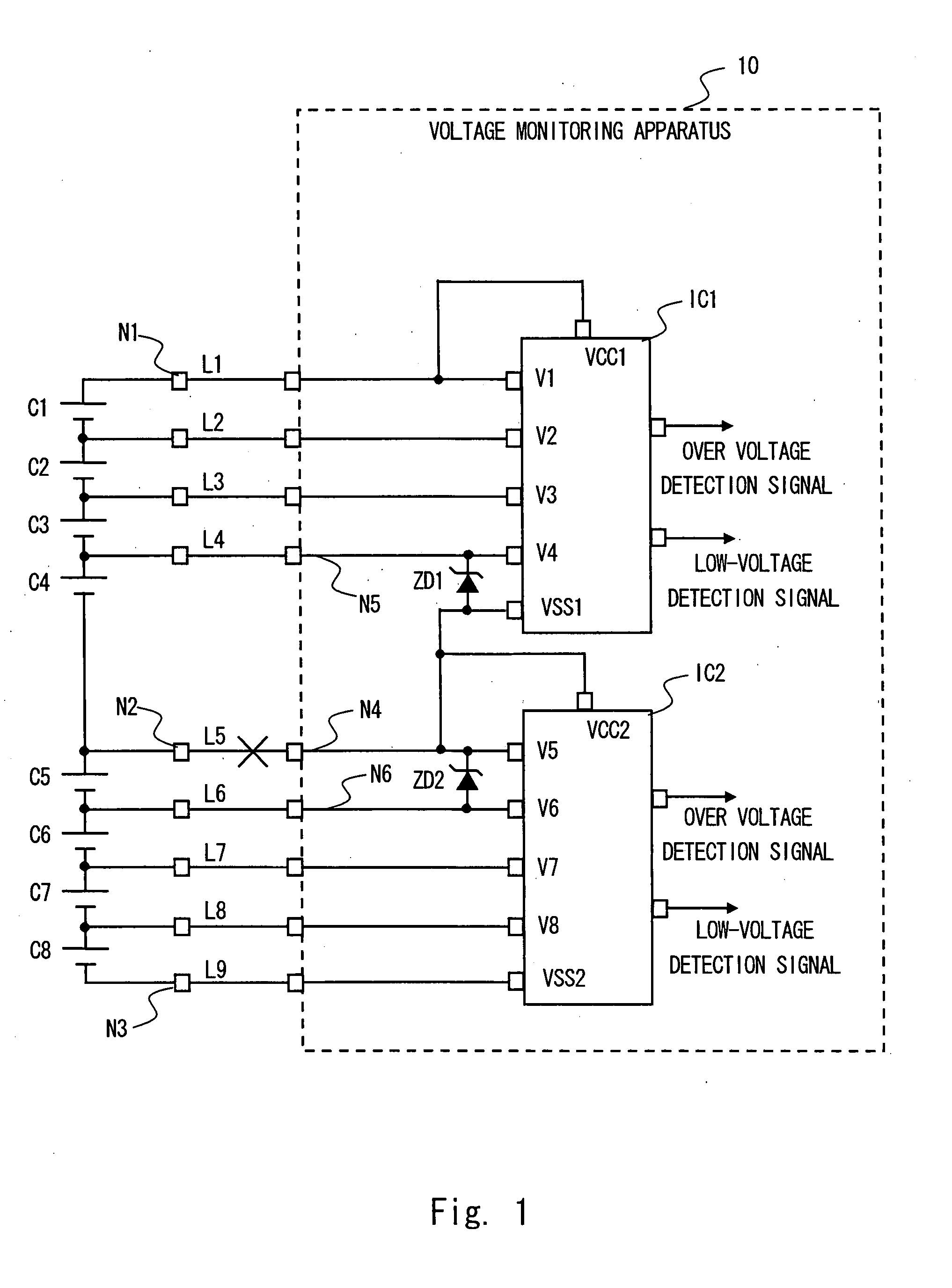
[0032]FIG. 1 is a schematic view showing a voltage monitoring apparatus 10 according to a first embodiment of the present invention. The voltage monitoring apparatus 10 of this embodiment includes a plurality of voltage sensor modules. The voltage sensor module is a device modularized of one or a plurality of voltage sensors. In this embodiment, one module is constituted by one semiconductor apparatus (IC). FIG. 1 is a view showing a case in which a voltage monitoring apparatus 10 includes two voltage sensor modules (hereinafter referred to as IC) IC1 and IC2. A first embodiment is described hereinafter in detail with an example of a case where one IC detects voltages of four battery cells.

[0033]As shown in FIG. 1, eight battery cells C1 to C8 monitored by the voltage monitoring apparatus 10 are connected in series. IC1 operates with a potential of a positive electrode of the battery cell C1 (see node N1 of FIG. 1) as a first power supply potential (upper power suppl...

Example

Second Embodiment

[0052]FIG. 8 is a schematic diagram showing a configuration of a voltage monitoring apparatus 20 according to a second embodiment of the present invention. FIG. 9 is a view showing a configuration of a voltage sensor module according to the second embodiment. In the second embodiment, the present invention is used to the voltage sensor modules IC1 and IC2 having a function to detect a disconnection in the line connecting the battery cells and the input terminals. In this embodiment, the Zener diode ZD1 of the first embodiment is not provided but the Zener diode ZD2 is provided only between the input terminals V5 and V6.

[0053]The inventors describe an IC with a function to detect a disconnection using the technique disclosed in Japanese Patent Application No. 2005-98596 (U.S. application Ser. No. 11 / 387,926). Firstly the IC having the disconnection detection function disclosed in Japanese Patent Application No. 2005-98596 is briefly described hereinafter. Components ...

Example

Third Embodiment

[0060]FIG. 10 is a schematic diagram showing a voltage monitoring apparatus according to a third embodiment of the present invention. This embodiment has SW1 and SW2 with inverted conductive and nonconductive conditions of the second embodiment. Without a disconnection in the line L5, the current source Iref8 of IC2 generates a current flows from the positive electrode of the battery cell 5 to VSS2. With the disconnection in the line L5, the potential of the node N4 decreases because the constant current source 8 continues to pass the constant current. Accordingly by inverting conductive conditions of SW1 and SW2 of the second embodiment, if the line L5 is disconnected, the potential of the node N4 decreases. Therefore, in the third embodiment, the Zener diode ZD1 is connected only between the input terminal V4 and the power supply terminal VSS1 of IC1. The clamping operation of the voltage between V4 and VSS1 by the Zener diode ZD1 is identical to the first embodime...


PUM


Abstract

A battery voltage monitoring apparatus to monitor a voltage of an assembled battery having a plurality of battery cells, the battery voltage monitoring apparatus comprises a first voltage sensor module having a voltage sensor and a first and a second module terminals connected to the voltage sensor, a second voltage sensor module having a voltage sensor different from the voltage sensor included in the first voltage sensor module and a third module terminal connected to the voltage sensor, a first terminal connected to the first and the third module terminals, a second terminal connected to the second module terminal, and a voltage clamp circuit to clamp a voltage between the first and the second terminals disposed between the first and the second terminals.

Description

INCORPORATION BY REFERENCE[0001]The-disclosure of U.S. application Ser. No. 11 / 387,926 filed on Mar. 24, 2006 including the specification, drawings and abstract is incorporated herein by reference in its entirety.BACKGROUND OF THE INVENTION[0002]1. Field of the invention[0003]The present invention relates to a battery voltage monitoring apparatus for detecting a battery voltage of a power supply apparatus composed of a plurality of secondary batteries connected in series, and particularly to a battery voltage monitoring apparatus for detecting a disconnection of a signal line when the line is disconnected while measuring a voltage.[0004]2. Description of the Related Art[0005]An electric car and a hybrid car are known as an environmental friendly vehicle. In the electric and hybrid cars, a motor is used as a driving source to drive vehicles. An electrifiable secondary battery is connected to the motor. A direct-current voltage obtained from the secondary battery is converted into an ...

Claims


Application Information

Patent Timeline
IPC IPC(8): H02J7/00
CPCH02J7/0016
Inventor MIYAMOTO, MANABU
Owner RENESAS ELECTRONICS CORP
Why Eureka
Try Eureka