Unlock instant, AI-driven research and patent intelligence for your innovation.

Apparatus and method for sensing objects proximate to fluid flows

a technology of sensing apparatus and fluid flow, applied in the field of sensing objects, can solve the problems of system not measuring the relative proximity of an object system cannot determine the degree of proximity to the flowing fluid, or the degree of insertion into the flowing fluid

Inactive Publication Date: 2007-08-16
MITSUBISHI ELECTRIC RES LAB INC
View PDF3 Cites 0 Cited by
  • Summary
  • Abstract
  • Description
  • Claims
  • Application Information

AI Technical Summary

Benefits of technology

[0013] Laminar flow ensures a consistent physical shape of the fluid, and also maintains electrical continuity. Thus, an electrical contact placed in the flowing stream provides an electrical connection to the entire stream. Any sufficiently conductive object that is placed near the stream will effectively form a capacitor with the fluid serving as one electrode, and the object as the other. The magnitude of this capacitive coupling will be roughly proportional to the area of the proximate surfaces and inversely proportional to the distance between them.
[0017] The electrical and optical sensing modes are independent and can be used singularly, or in combination at any time. Because the two techniques work best at different distances, using both concurrently enables a greater working range.
[0018] Furthermore, it is possible to detect where the object is along the fluid flow, that is, the distance from the nozzle to the object measured along the fluid flow.

Problems solved by technology

However, that system does not measure the relative proximity of an object to the flowing fluid, in a general sense.
That system cannot determine a degree of proximity to the fluid flow, or a degree of insertion into the fluid flow.

Method used


Image

  • Apparatus and method for sensing objects proximate to fluid flows
  • Apparatus and method for sensing objects proximate to fluid flows
  • Apparatus and method for sensing objects proximate to fluid flows

Examples


Embodiment Construction

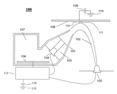
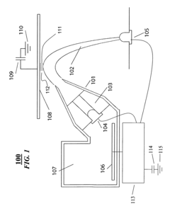
[0023]FIG. 1 shows an apparatus 100 for measuring a proximity of an object 108 to a fluid flow 102 according to one embodiment of the invention. That is, the apparatus measures the width of an air gap 111 between the object 108 and the fluid flow 102. A nozzle 101 produces the flow of the fluid 102 having a laminar flow. The fluid is obtained from a suitable fluid source 107. It should be noted, that the flow does not need to be perfectly laminar. Any flow that is sufficiently uniform over time to maintain substantially constant electrical and optical characteristics suffices.

[0024] Two mechanisms, one electrical and the other optical, are used to accommodate measuring a large range of distances. A light source 104 is suitably arranged to allow light to travel through the fluid flow 102, due to internal reflection. Hence, the fluid flow serves as an optical waveguide. The light source 104 is held in place by flow straightening fins 103 so that the light source does not impede lamin...


PUM


Abstract

An apparatus senses an object proximate to a laminar fluid flow by using the fluid as part of the sensing system. For more distant objects, an electrical system detects the capacitance between the proximate object and the flowing fluid via an impedance measurement. For objects touching the flow, an optical system detects the loss of total internal reflection. Together, the two systems allow the proximity to be determined over a wide range. A fluid flow is produced through a nozzle. An electrode is placed in the fluid. A complex impedance is measured between the electrode and an object due to capacitive coupling between the object and the fluid flow. The complex impedance is inversely proportional to a distance between the object and the fluid flow and proportional to an area of proximity of the object.

Description

FIELD OF THE INVENTION [0001] This invention relates generally to sensing objects, and more particularly to sensing objects proximate to fluid flows. BACKGROUND OF THE INVENTION [0002] Laminar fluid flow occurs when velocity and pressure characteristics of a fluid are substantially constant over time. A useful consequence of this property is that electro-optical characteristics of the fluid are also relatively constant. Laminar flow is easy to recognize in practice by its smooth flowing appearance. [0003] In many applications, it is desired to determine the proximity and / or contact of an object to a fluid flow. Examples include various coating processes. Many types of sensors can be used to determine the relative positions of the fluid and the object, and thus their relative spacing. [0004] There are many known methods for determining proximity and / or contact to a static fluid. For example, the Dwyer Model 1430, Microtector Electronic Point Gage, manufactured by Dwyer Instruments, I...

Claims


Application Information

Patent Timeline
IPC IPC(8): G01R27/26
CPCG01V8/10G01V3/088
Inventor DIETZ, PAUL H.WESTHUES, JONATHANLEIGH, DARREN L.
Owner MITSUBISHI ELECTRIC RES LAB INC