Power efficient wireless transmission

a wireless transmission and wireless technology, applied in the field of power efficient transmission, can solve the problems of insufficient power supply of network elements, insufficient power output capacity of power sources mentioned above, and insufficient power consumption of a standard base station of a global system for mobile communications transmitting continuously with even one transmitter, etc., to achieve better radio access network quality, lower interference in radio access network, and lower power consumption of transmitters

Inactive Publication Date: 2007-08-16
RPX CORP
View PDF6 Cites 48 Cited by
  • Summary
  • Abstract
  • Description
  • Claims
  • Application Information

AI Technical Summary

Benefits of technology

[0015] The invention provides several advantages. The power consumption of the transmitter is lower by virtue of the power adjustment related to the time slots comprising no data or control signal to be transmitted. Accordingly, limited power resources, such as batteries providing power to the transmitter, will work for longer periods. Additionally, the quality of the radio access network will be better, since the interference in the radio access network will be lower due to the power adjustment. This increases the capacity of the radio access network and improves quality of service.

Problems solved by technology

In radio access networks and environments, there may arise situations in which power sources of network elements may not provide enough power for the network elements.
The power sources mentioned above may lack power output capacity, if a continuous high power output capacity is required.
For example, the power consumption of a standard base station of a GSM (Global System for Mobile Communications) transmitting continuously with even only one transmitter may be too high for a solar cell power generator.

Method used


Image

  • Power efficient wireless transmission
  • Power efficient wireless transmission
  • Power efficient wireless transmission

Examples


Embodiment Construction

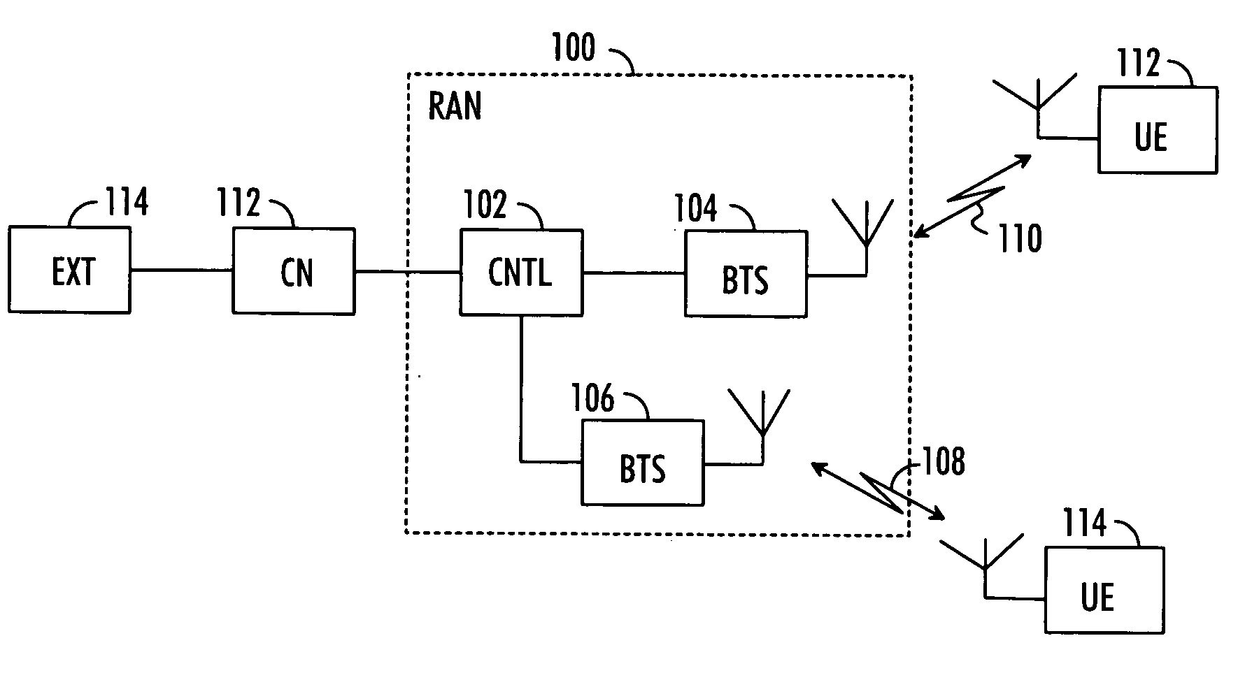
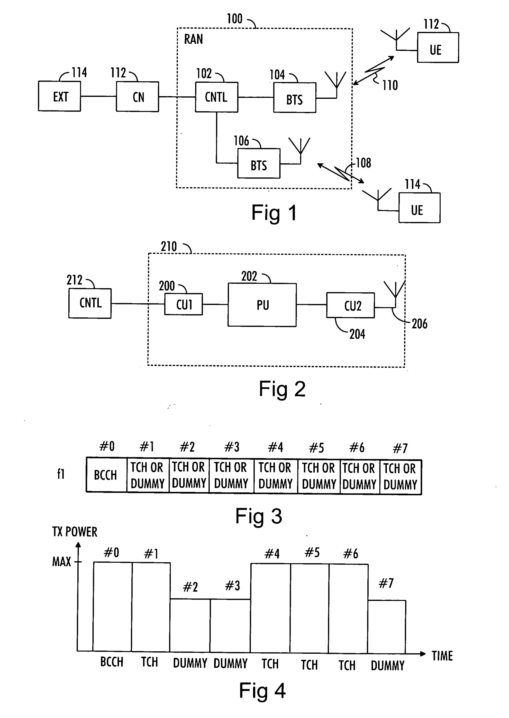
[0026] With reference to FIG. 1, let us examine an example of a wireless telecommunication system in which embodiments of the invention can be applied. In the wireless telecommunication system, the data transmission on a given frequency band is divided into a plurality of time slots. Accordingly, one or more time slots are allocated to data to be transmitted and the data is transmitted in the allocated time slots. The wireless telecommunication system may preferably be a GSM-based cellular telecommunication system but the invention may be implemented in other cellular telecommunication systems, too.

[0027] The network elements of the telecommunication system of FIG. 1 can be grouped into a radio access network (RAN) 100 that handles all radio-related functionalities of the system, and a core network (CN) 112 which takes care of switching and routing calls and data connections to external networks 114. The external network may be, for example, the Internet, Integrated Services Digita...


PUM


Abstract

A solution for power efficient transmission in a wireless telecommunication system is provided. The telecommunication system utilizes a time slot based data transmission scheme. According to the provided solution, at least a portion of time slots is allocated to a broadcast control channel on a given frequency and to at least one different channel. The transmit power levels of the time slot or time slots allocated to another channel or other channels than the broadcast control channel are then adjusted on the basis of contents of the time slots. The broadcast signal is then transmitted with a given transmit power level on a time slot allocated to the broadcast control channel, and a signal or signals on other time slots are transmitted with the adjusted transmit power level.

Description

FIELD [0001] The invention relates to a power efficient transmission in a wireless telecommunication system. BACKGROUND [0002] In radio access networks and environments, there may arise situations in which power sources of network elements may not provide enough power for the network elements. In rural environments, for example, there may be areas where traffic is low or very low and air interface capacity provided by the radio access network is mostly free. In such environments, a solar cell power generator or another solution without long wires to mains may be used. Another network element providing radio coverage is a repeater which may also use weak power sources. Weak power sources may also be used as a back up power source for power failure in the mains power supply. The power sources mentioned above may lack power output capacity, if a continuous high power output capacity is required. For example, the power consumption of a standard base station of a GSM (Global System for M...

Claims


Application Information

Patent Timeline
Patent Type & Authority Applications(United States)
IPC IPC(8): H04B1/04H04B7/00H04W52/16H04W52/32H04W52/40H04W88/08
CPCH04W52/16H04W52/322Y02B60/50H04W88/08H04W52/40
Inventor SUONVIERI, JUKKA
Owner RPX CORP
Why Eureka
Try Eureka