[0017] With the above described prior art as a background, and also considering he relevant background with respect to synthetic
beamforming techniques for slotted transducers, in accordance with one aspect of the invention, ultrasonic devices (whether single elements or arrays) that are used for imaging and that employ capacitive micromachined membranes are greatly improved through the implementation of novel methods of mapping transducer surfaces so as to customize the
acoustic radiation of the transducer apertures according to the requirements of high quality or
harmonic imaging systems and so as to enhance the
electrical impedance characteristics of the transducer devices with respect to the associated
electronics.
[0018] Another aspect of the present invention concerns the provision of a method of shaping a CMUT device which includes customized optimization or
apodization (weighting) of the CMMs forming the transducer surface. Preferably, the apodization of the CMMs is performed in amplitude and / or in frequency to enhance the quality of the acoustic
beam pattern and, in particular, so as to decrease the side lobes (for arrays) or the lateral lobes (for single surfaces) of the devices.
[0022] In accordance with another aspect thereof, the present invention relates to particular
surface mapping configurations of a Capacitive Micromachined Ultrasonic
Transducer (CMUT) where Capacitive Micromachined Membranes (CMM) are specifically tailored and arranged on the front surface of the transducer device so as to enable customization of the acoustical and electrical behavior of the device. The method of this aspect of the invention is well suited to arrayed imaging transducers wherein the characteristics of the individual transducers are crucial in achieving quality images. However, the method is also applicable to single surface (area) transducing devices, and when so implemented, this method prevents
edge effects and significantly improves the acoustical
beam pattern and / or
frequency response, thereby enabling a designer to custom shape of the acoustical output of the transducer device whatever the
footprint of device.
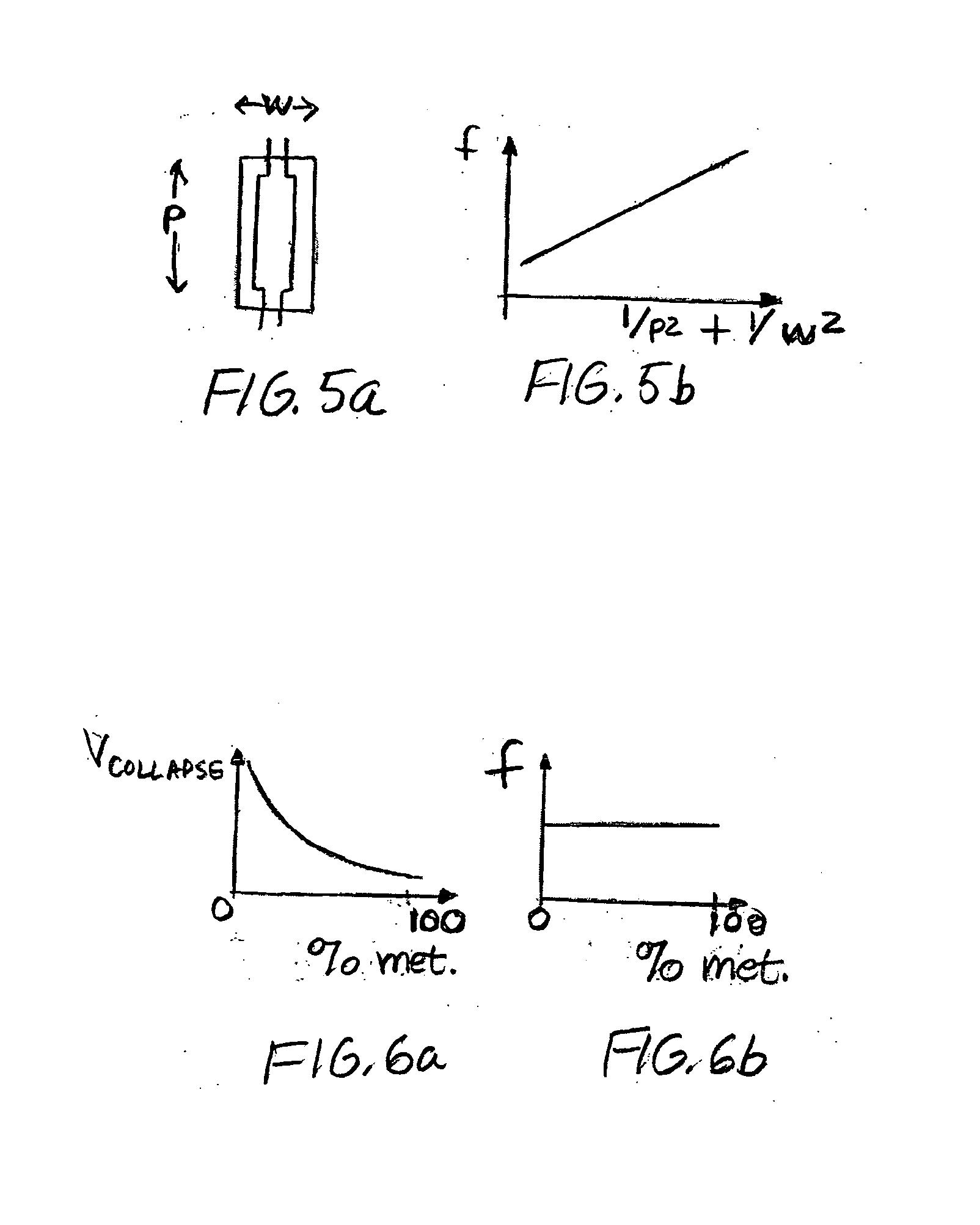
[0023] In another aspect of the invention, the arrangement of the CMMs over the surface CMUT provides the surface with an optimized apodization function, thus improving the output acoustical beam pattern. The apodization functions that can be employed include those based on well known
gaussian or hamming distribution functions commonly used in advanced imaging. Advantageously, the apodization obtained with specific sampling of the CMMs can be used to simultaneously control both the amplitude and resonant frequency of the transducer device without any compromising of the intrinsic performance of the device.
[0024] Yet another aspect of the invention concerns apodization of the elemental apertures of array transducers. Generally speaking, an
array transducer designed for use in imaging applications is comprised of a plurality of independently individually addressable elements or element apertures. In accordance with this aspect of the present invention, the addressable elements are individually formed by a plurality of CMMs having a shape and an area which are optimized to provide an amplitude and frequency apodization function in both the
azimuth and elevation directions. Application of this method to transducer array devices provides a customized
smoothing of the physical boundaries of the transducer elements, thereby preventing the occurrence of side lobes.
[0025] A further aspect of the invention is concerned with an improvement of the electrical behavior of the CMUT devices, particularly in arrayed transducer constructions wherein the transducer elements are of very narrow dimensions and the
electrical impedance thereof is inherently highly mismatched to that of the
transmission line, thereby creating spurious reflections and
signal disturbances that affect the pulse shape and
frequency response accordingly. The physical characteristics of the CMMs are tailored so as to maximize the
capacitance of the membranes, thereby enhancing the efficiency of the elements of the transducer array. The value of the
electrical impedance (specifically, the imaginary part) of the array elements is, therefore, reduced, and thus the elements are seen as more resistive than in conventional CMUT designs.

