
Control System For Hydrogen Addition Internal Combustion Engine

Inactive Publication Date: 2007-08-23
TOYOTA JIDOSHA KK
View PDF4 Cites 3 Cited by
  • Summary
  • Abstract
  • Description
  • Claims
  • Application Information

AI Technical Summary

Benefits of technology

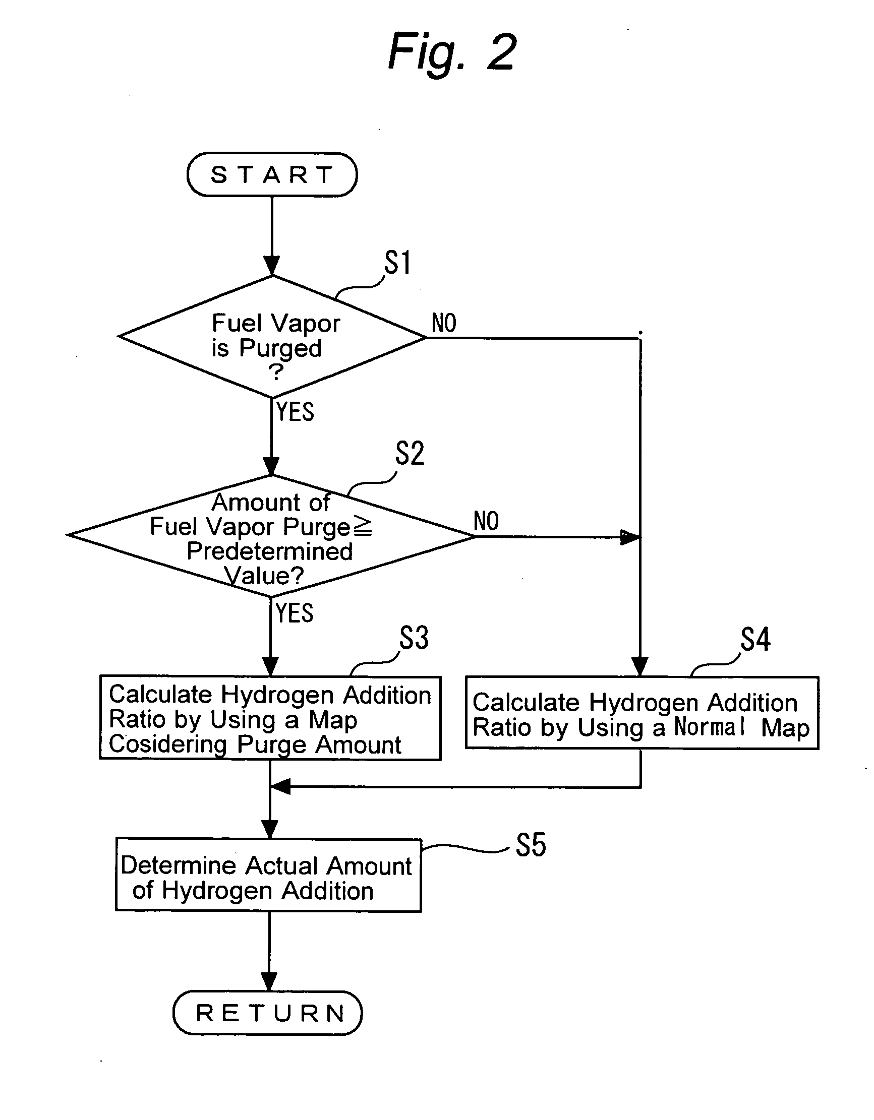
[0008] According to first aspect of the present invention, a control system for a hydrogen addition internal combustion engine that uses hydrocarbon fuel and hydrogen gas as combustion fuel, the control system comprises a canister, purge means, hydrogen addition ratio setup means, and hydrogen gas addition ratio adjustment means. The canister adsorbs fuel vapor generated in a tank for storing the hydrocarbon fuel. The purge means purges the fuel vapor into an intake path of the hydrogen addition internal combustion engine in a predefined situation. The hydrogen addition ratio setup means sets the ratio of hydrogen gas addition to the hydrocarbon fuel. The hydrogen gas addition ratio adjustment means increases the ratio of hydrogen gas addition when the fuel vapor is purged into the intake path.
[0009] When the fuel vapor is purged into the intake path, the first aspect of the present invention increases the ratio of hydrogen gas addition. It is therefore possible to inhibit the combustion state in a cylinder from deteriorating due to the fuel vapor purge. As a result, good emission and driveability can be offered during a fuel vapor purge.
[0010] According to a second aspect of the present invention, there is provided the control system for a hydrogen addition internal combustion engine, which is improved as described above, wherein the hydrogen gas addition ratio adjustment means increases the ratio of hydrogen gas addition when the amount of fuel vapor purge into the intake path is not smaller than a predetermined value.
[0011] when the amount of fuel vapor purge into the intake path is not smaller than a predetermined value, the second aspect of the present invention increases the ratio of hydrogen gas addition. It is therefore possible to suppress the hydrogen use under the situation that the amount of fuel vapor purge is very little and that the combustion state is not influenced much by fuel vapor purge.

Problems solved by technology

However, if the internal combustion engine includes a canister for adsorbing vaporized fuel (fuel vapor) in a gasoline tank, the amount of vaporized fuel purged from the canister to an intake path cannot be accurately controlled.
Therefore, even when hydrogen gas is supplied, unstable combustion results.
It is difficult to accurately control the air-fuel ratio in an engine cylinder particularly when a large amount of vaporized fuel is purged from the canister to the intake path.
Unstable combustion then results, thereby causing emission and driveability to deteriorate.

Method used


Image

  • Control System For Hydrogen Addition Internal Combustion Engine
  • Control System For Hydrogen Addition Internal Combustion Engine
  • Control System For Hydrogen Addition Internal Combustion Engine

Examples


Embodiment Construction

[0015] An embodiment of the present invention will now be described with reference to the accompanying drawings. Like elements in the drawings are designated by like reference numerals and will not be described repeatedly. The present invention is not limited to the embodiment described below.

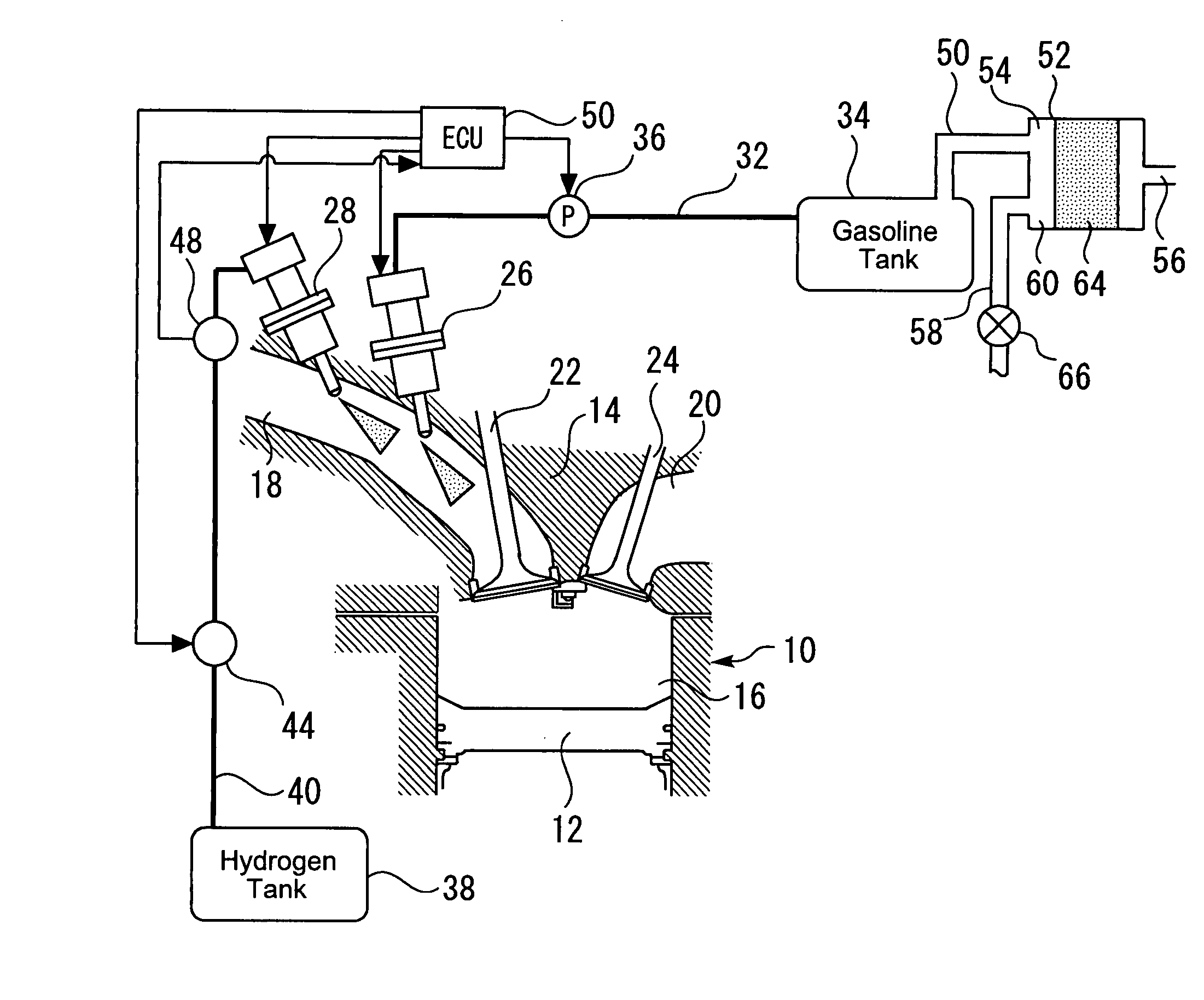
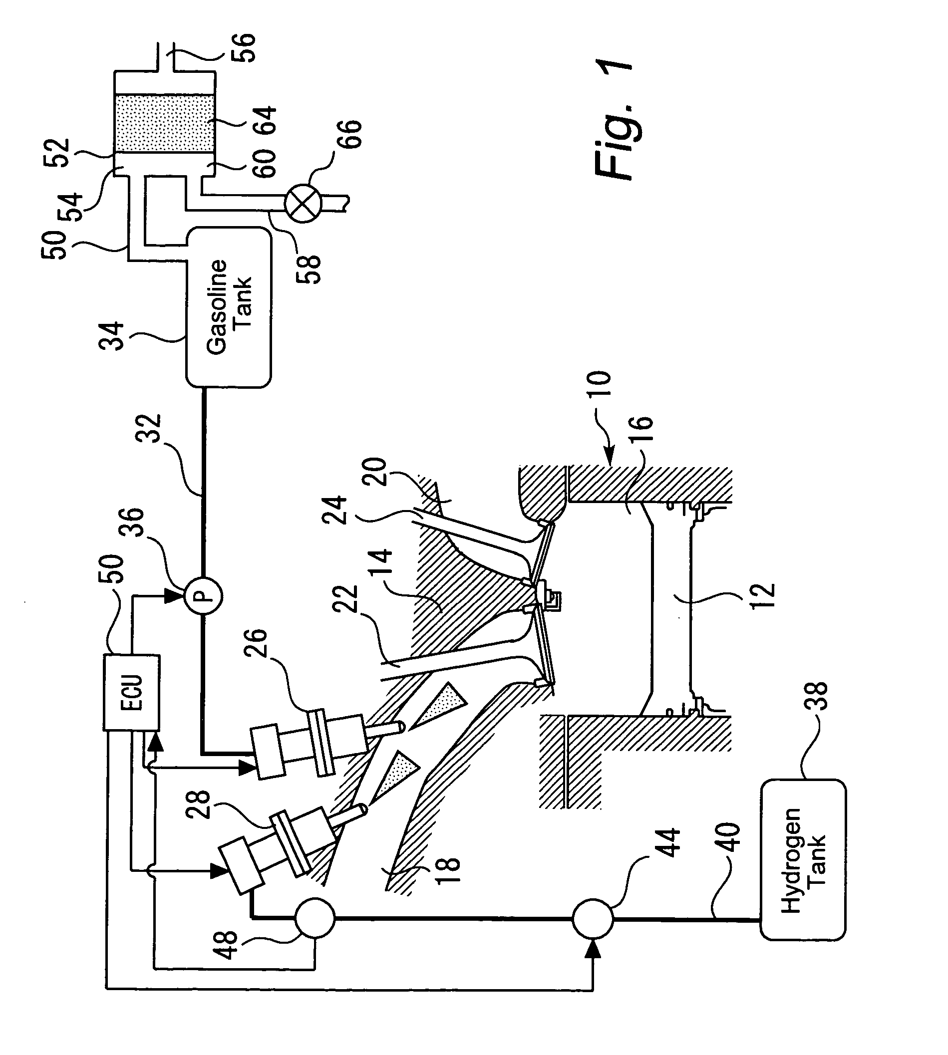
[0016]FIG. 1 illustrates the configuration of a system that is equipped with a hydrogen addition internal combustion engine 10 according to an embodiment of the present invention. A cylinder of the internal combustion engine 10 contains a piston 12, which reciprocates within the cylinder. The internal combustion engine 10 also includes a cylinder head 14. A combustion chamber 16 is formed between the piston 12 and cylinder head 14. The combustion chamber 16 communicates with an intake port 18 and an exhaust port 20. The intake port 18 and exhaust port 20 are respectively provided with an intake valve 22 and an exhaust valve 24.

[0017] The intake port 18 is provided with a gasoline injection va...


PUM


Abstract

Disclosed is a control system for a hydrogen addition internal combustion engine that uses hydrocarbon fuel and hydrogen gas as combustion fuel. The control system includes a canister 52 for adsorbing fuel vapor generated in a tank 34 for storing the hydrocarbon fuel; a purge VSV 66 for purging the fuel vapor into an intake port 18 of the hydrogen addition internal combustion engine in a predefined situation; hydrogen addition ratio setup means for setting the ratio of hydrogen gas addition to the hydrocarbon fuel; and hydrogen gas addition ratio adjustment means for increasing the ratio of hydrogen gas addition when the fuel vapor is purged into the intake port 18.

Description

TECHNICAL FIELD [0001] The present invention relates to a control system for a hydrogen addition internal combustion engine. BACKGROUND ART [0002] It is known that an internal combustion using gasoline as fuel reduces the amount of nitrogen oxide (NOx ) in an exhaust gas when hydrogen gas is supplied in addition to gasoline. A technology disclosed, for instance, by Japanese Patent Laid-open No. 2004-116398 determines the hydrogen addition ratio so as to reduce the NOX exhaust amount, and operates an internal combustion engine by injecting gasoline and hydrogen in accordance with the determined ratio. [Patent Document 1][0003] Japanese Patent Laid-open No. 2004-116398 [Patent Document 2][0004] Japanese Patent Laid-open No. Hei 6-200805 [0005] However, if the internal combustion engine includes a canister for adsorbing vaporized fuel (fuel vapor) in a gasoline tank, the amount of vaporized fuel purged from the canister to an intake path cannot be accurately controlled. Therefore, ev...

Claims


Application Information

Patent Timeline
IPC IPC(8): F02B43/00F02M25/08F02D19/08F02D41/00F02M21/02F02M25/00
CPCF02B2275/16F02D19/081F02D41/0027F02D41/0032F02D41/3094Y10S123/12F02M25/12Y02T10/36F02D19/0644F02D19/0692F02M25/089Y02T10/30
Inventor ITO, YASUSHI
Owner TOYOTA JIDOSHA KK
Learn More