
Liquid jetting head and method for producing the same

a jetting head and liquid technology, applied in the direction of printing, inking apparatus, etc., can solve the problems of difficult air discharge, difficult diffusion bonding, and insufficient transfer of pressing force to the base plate, so as to reduce the thickness, suppress crosstalk, and reduce the drive voltage

Active Publication Date: 2007-08-23
BROTHER KOGYO KK
View PDF3 Cites 4 Cited by
  • Summary
  • Abstract
  • Description
  • Claims
  • Application Information

AI Technical Summary

Benefits of technology

[0007] Accordingly, an object of the present invention is to provide a liquid jetting head which makes it difficult for air to stay inside a pressure chamber, thereby suppressing deterioration of liquid jetting performance, and to provide a method of producing the same.
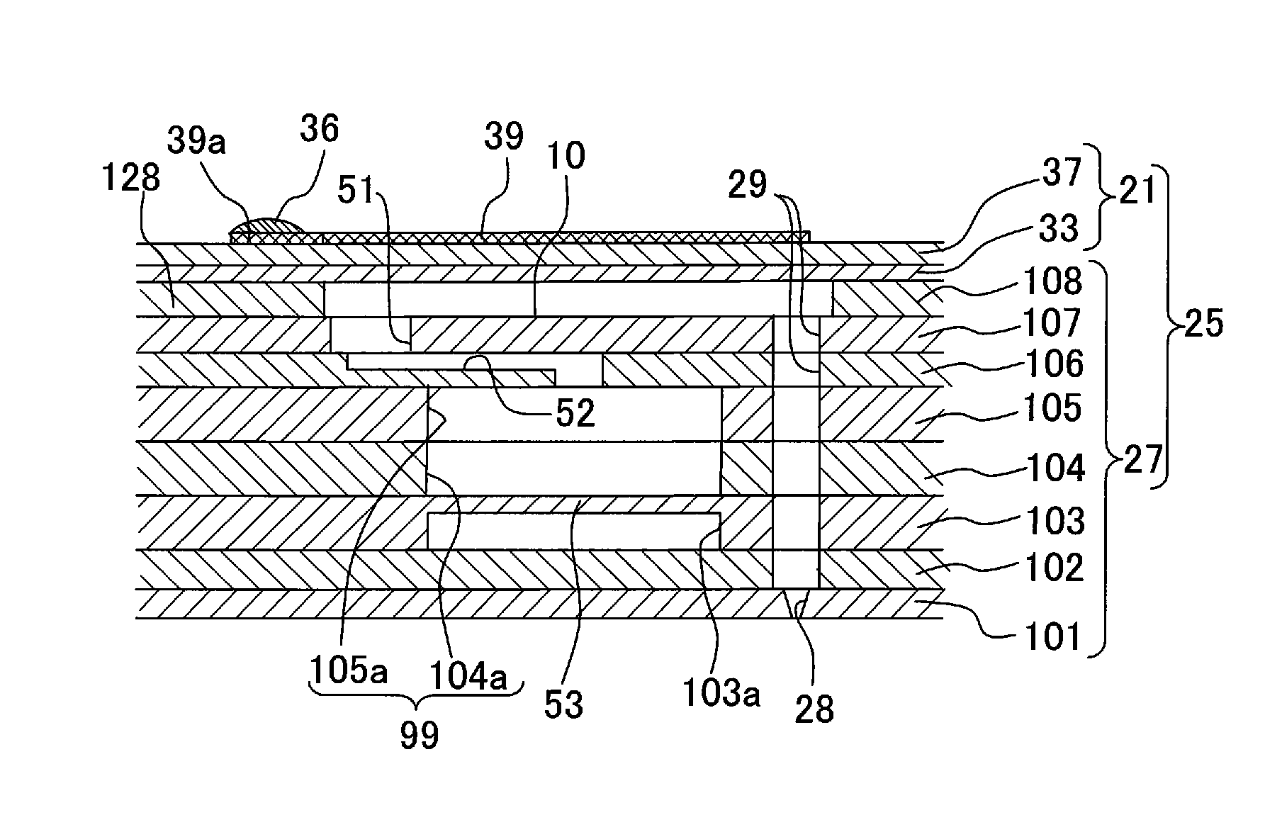
[0025] In the method of producing the liquid jetting head according to the present invention, in the space forming step, the space may be formed in the vibration plate. The liquid jetting head partially deforms the vibration plate facing the pressure chambers and the piezoelectric layer to change the volumes of the pressure chambers, thereby applying pressure to liquid inside the pressure chambers. When the space is formed in the vibration plate in the gap forming step, the area of the vibration plate at which the space is formed has a decreased thickness. Then, the partial deformation of the vibration plate and the piezoelectric layer, which are facing a certain pressure chamber among the pressure chambers, is hardly propagated to a portion facing another pressure chamber adjacent to the certain pressure chamber. Therefore, the crosstalk can be suppressed. In addition, the wall surface-vicinity areas on the other surface of the pressure chamber plate and areas of the vibration plate which overlap the wall surfaces of the partition wall, in the direction orthogonal to the plane, are bonded securely. Accordingly, since the deformation of the vibration plate and the piezoelectric layer facing the pressure chambers becomes stable, the drive voltage can be lowered and the power consumption can be lowered.

Problems solved by technology

At this time, for a space between the cavity plate and the base plate, the pressing force is sufficiently transferred to the base plate in a center portion of a partition wall defining pressure chambers, but the pressing force is not sufficiently transferred to the base plate in the vicinity of a wall surface of the partition wall defining the pressure chambers.
Thus, there is a fear that the diffusion-bonding is carried out in a state that the base plate and a portion in the vicinity of the wall surface of the partition wall are not in contact.
When ink is filled in an ink-jet head having such a gap and air enters this gap, then it is difficult to discharge the air even by purging, and the air remains inside the pressure chamber.
As a result, desired ink jetting performance cannot be obtained.

Method used


Image

  • Liquid jetting head and method for producing the same
  • Liquid jetting head and method for producing the same
  • Liquid jetting head and method for producing the same

Examples


Embodiment Construction

[0041] Hereinafter, a preferred embodiment of the present invention will be explained with reference to the drawings.

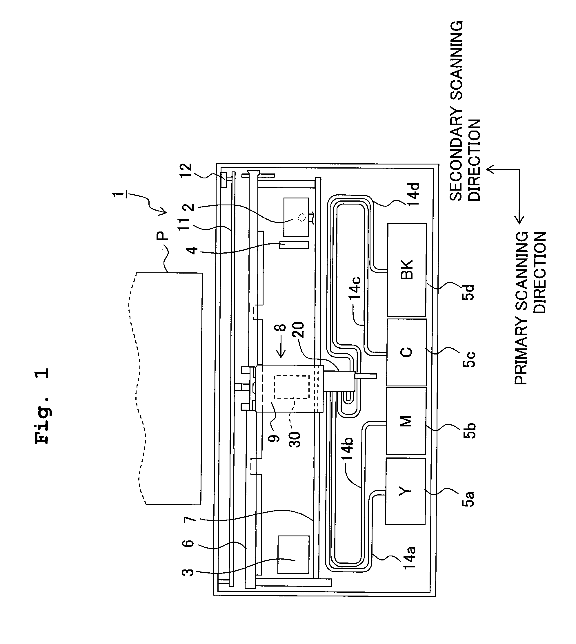
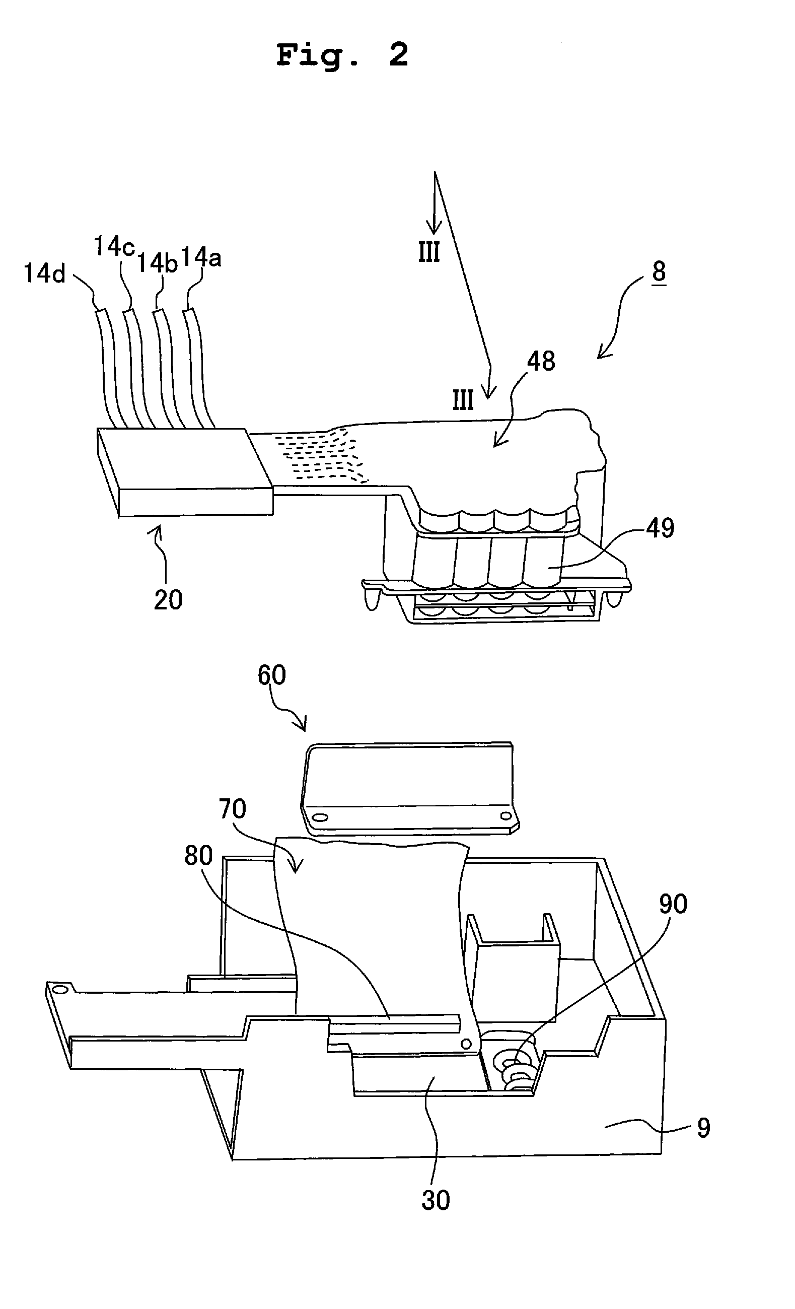
[0042] This embodiment is an example in which the present invention is applied to an ink-jet head as a liquid jetting head which jets ink from nozzles to a recording paper. FIG. 1 is a schematic plan view of an ink-jet printer adopting an ink-jet head according to the embodiment of the present invention. Inside the ink-jet printer 1, as shown in FIG. 1, two guide shafts 6, 7 are provided. On these guide shafts 6, 7, a head unit 8 which serves also as a carriage is attached. The head unit 8 includes a head holder 9 formed of a synthetic resin material. The head holder 9 holds an ink-jet head 30 which performs printing by jetting ink onto a print sheet P. The head holder 9 is attached to a belt 11 which is rotated by a carriage motor 12, and the head holder 9 reciprocates in a primary scanning direction along the guide shafts 6, 7 by being driven by the carriage motor ...


PUM


Abstract

An ink-jet head includes a channel unit and a piezoelectric actuator. The channel unit has a plurality of plates made of metal and including a cavity plate which is made of metal and in which a plurality of pressure chambers are formed and a supply plate which is made of metal and in which holes communicating with the pressure chambers respectively are formed, and the plates are diffusion-bonded with each other. The piezoelectric actuator has a vibration plate which is diffusion-bonded with the cavity plate. A groove is formed in a partition wall defining the pressure chambers or in an area overlapping the partition wall of the vibration plate, the cavity plate, and the supply plate. There is provided a liquid jetting head in which air hardly remains in the pressure chambers, and deterioration of jetting performance by the air is suppressed.

Description

CROSS-REFERENCE TO RELATED APPLICATIONS [0001] The present application claims priority from Japanese Patent Application No. 2005-250797 filed on Aug. 31, 2005, the disclosure of which is incorporated herein by reference in its entirety. BACKGROUND OF THE INVENTION [0002] 1. Field of the Invention [0003] The present invention relates to a liquid jetting head which jets liquid and a method of producing the same. [0004] 2. Description of the Related Art [0005] As a liquid jetting head, for example, there is an ink-jet head which jets ink. The ink-jet head has a plurality of complicated and elaborate ink channels inside. Such an ink-jet head is formed, for example, by stacking thin etching plates. For securely bonding the stacked etching plates with one another, it is conceivable to bond the plates using, for example, an adhesive that is epoxy based, acrylic based or the like. However, when the amount of an adhesive applied is large, the adhesive may flow into an ink channel or the like...

Claims


Application Information

Patent Timeline
Patent Type & Authority Applications(United States)
IPC IPC(8): B41J2/045
CPCB41J2002/14459B41J2202/11B41J2002/14419B41J2002/14306B41J2002/14362B41J2/14233
Inventor KATAYAMA, NAOKISUGAHARA, HIROTO
Owner BROTHER KOGYO KK
Learn More