Apparatus and method for maintaining immersion fluid in the gap under the projection lens during wafer exchange in an immersion lithography machine

a technology of immersion lithography and immersion fluid, which is applied in the field of apparatus and method for maintaining immersion fluid in the gap under the projection lens during wafer exchange in the immersion lithography machine, can solve the problems of reducing yield, causing bubbles to form within the immersion fluid, and affecting the effect of wafer exchang

Inactive Publication Date: 2007-08-23
NIKON CORP
View PDF98 Cites 35 Cited by
  • Summary
  • Abstract
  • Description
  • Claims
  • Application Information

AI Technical Summary

Benefits of technology

[0007] An apparatus and method maintain immersion fluid in the gap adjacent to the projection lens in a lithography machine. The apparatus and method include an optical assembly that projects an image onto a work piece and a stage assembly including a work piece table that supports the work piece adjacent to the optical assembly. An environmental system is provided to supply and remove an immersion fluid from the gap. After exposure of the work piece is complete, an exchange system removes the work piece and replaces it with a second work piece. An immersion fluid containment system is provided to maintain the immersion fluid in the gap when the work piece table moves away from the projection lens. The gap therefore does not have to be refilled with immersion fluid when the first work piece is replaced with a second work piece.

Problems solved by technology

Wafer exchange with immersion lithography as described above is problematic for a number of reasons.
The repeated filling and draining of the gap may cause variations in the immersion fluid and may cause bubbles to form within the immersion fluid.
Bubbles and the unsteady fluid may interfere with the projection of the image on the reticle onto the wafer, thereby reducing yields.
The overall process also involves many steps and is time consuming, which reduces the overall throughput of the machine.

Method used


Image

  • Apparatus and method for maintaining immersion fluid in the gap under the projection lens during wafer exchange in an immersion lithography machine
  • Apparatus and method for maintaining immersion fluid in the gap under the projection lens during wafer exchange in an immersion lithography machine
  • Apparatus and method for maintaining immersion fluid in the gap under the projection lens during wafer exchange in an immersion lithography machine

Examples


Embodiment Construction

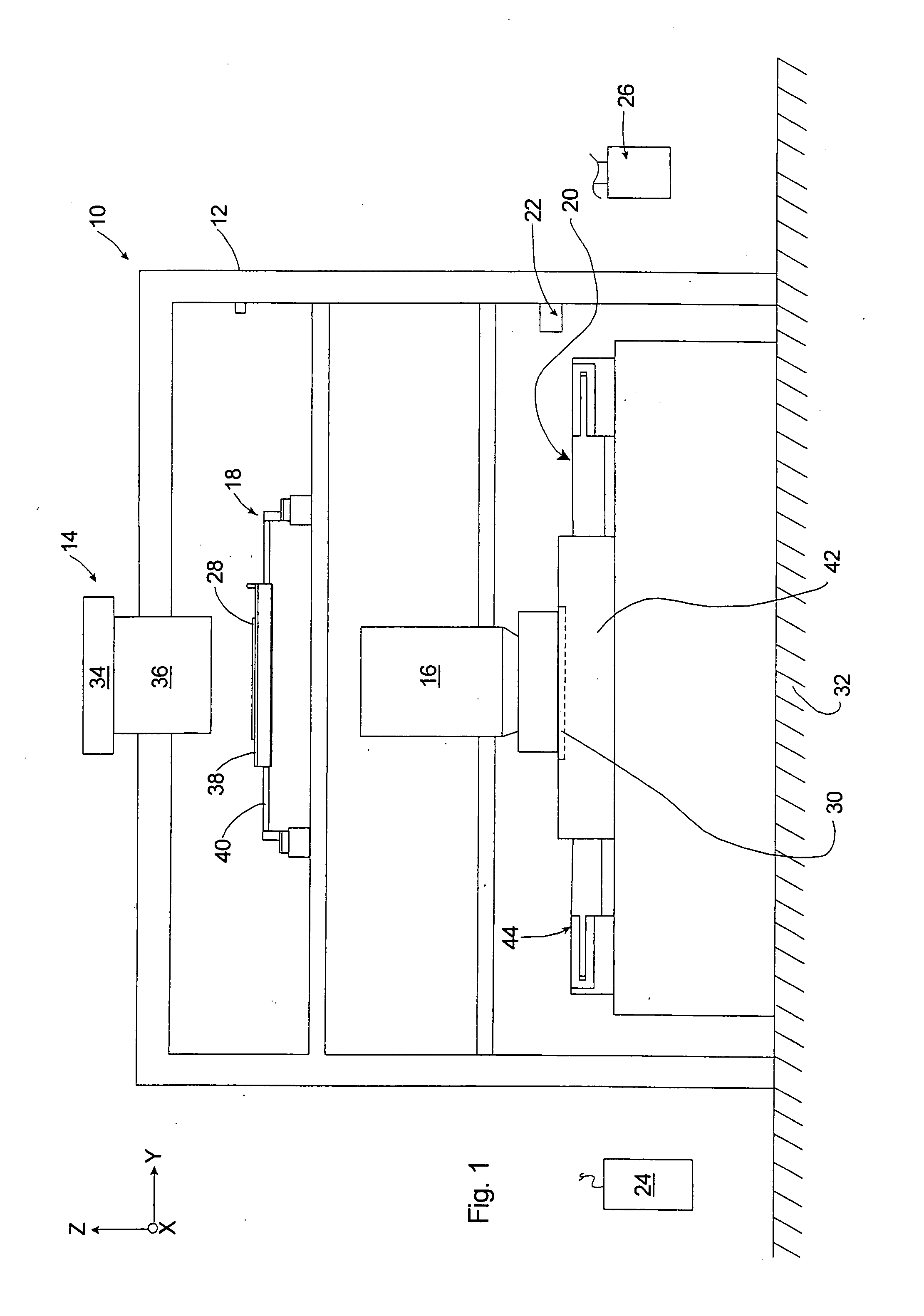
[0018]FIG. 1 is a schematic illustration of a lithography machine 10 having features of the invention. The lithography machine 10 includes a frame 12, an illumination system 14 (irradiation apparatus), an optical assembly 16, a reticle stage assembly 18, a work piece stage assembly 20, a measurement system 22, a control system 24, and a fluid environmental system 26. The design of the components of the lithography machine 10 can be varied to suit the design requirements of the lithography machine 10.

[0019] In one embodiment, the lithography machine 10 is used to transfer a pattern (not shown) of an integrated circuit from a reticle 28 onto a semiconductor wafer 30 (illustrated in phantom). The lithography machine 10 mounts to a mounting base 32, e.g., the ground, a base, or floor or some other supporting structure.

[0020] In various embodiments of the invention, the lithography machine 10 can be used as a scanning type photolithography system that exposes the pattern from the retic...


PUM

PropertyMeasurementUnit
of wavelengthaaaaaaaaaa
heightaaaaaaaaaa
sizeaaaaaaaaaa

Abstract

An apparatus and method maintain immersion fluid in the gap adjacent to the projection lens during the exchange of a work piece in a lithography machine. The apparatus and method include an optical assembly that projects an image onto a work piece and a stage assembly including a work piece table that supports the work piece adjacent to the optical assembly. An environmental system is provided to supply and remove an immersion fluid from the gap between the optical assembly and the work piece on the stage assembly. After exposure of the work piece is complete, an exchange system removes the work piece and replaces it with a second work piece. An immersion fluid containment system maintains the immersion liquid in the gap during removal of the first work piece and replacement with the second work piece.

Description

RELATED APPLICATIONS [0001] This is a Divisional of U.S. patent application Ser. No. 11 / 237,721 filed Sep. 29, 2005, which in turn is a Continuation of International Application No. PCT / IB2004 / 001259 filed Mar. 17, 2004, which claims the benefit of U.S. Provisional Application No. 60 / 462,499 filed on Apr. 11, 2003. The entire disclosures of the prior applications are incorporated herein by reference in their entireties.BACKGROUND [0002] Lithography systems are commonly used to transfer images from a reticle onto a semiconductor wafer during semiconductor processing. A typical lithography system includes an optical assembly, a reticle stage for holding a reticle defining a pattern, a wafer stage assembly that positions a semiconductor wafer, and a measurement system that precisely monitors the position of the reticle and the wafer. During operation, an image defined by the reticle is projected by the optical assembly onto the wafer. The projected image is typically the size of one or...

Claims


Application Information

Patent Timeline
Patent Type & Authority Applications(United States)
IPC IPC(8): G03B27/42G02BG03B27/32G03B27/58G03F7/20
CPCG03B27/52G03F7/70733G03F7/70716G03F7/70341G03F7/2041G03F7/20H01L21/0274G03F7/70725G03F7/2055G03F7/30G03F7/70833G03F7/2063H01L21/0273G03F7/2012
Inventor BINNARD, MICHAEL
Owner NIKON CORP
Why Eureka
Try Eureka