Stacked-cell display with field isolation layer

a technology of field isolation layer and stacking cell, applied in the field of stacking cell display, can solve the problems of inability to address crosstalk between electrophoretic cells arranged in stacks, inability to solve crosstalk, and inability to increase so as to maximize the distance between the first and second electrodes

Inactive Publication Date: 2007-08-23
EASTMAN KODAK CO
View PDF15 Cites 58 Cited by
  • Summary
  • Abstract
  • Description
  • Claims
  • Application Information

AI Technical Summary

Benefits of technology

[0032] wherein the first and second imaging materials substantially lie between the first and second in-plane electrodes, thereby substantially maximizing the distance between the first and second electrodes.

Problems solved by technology

However, as is well known in the signal processing art, an electrical field of some level that is generated at one component can have some impact on neighboring components, causing the undesirable phenomenon known as “crosstalk.” As devices are further miniaturized and electrodes are spaced more tightly as a result, this problem can become more acute.
Thus, it is likely that there can be some crosstalk interaction between neighboring cells in the stack of electrophoretic cells when using this type of stacked cell configuration.
Crosstalk problems would also be likely for staggered stacked cell arrangements, such as those described in U.S. Pat. No. 6,788,452 entitled “Process for Manufacture of Improved Color Displays” and U.S. Publication No. 2004 / 0169912 entitled “Electrophoretic Display and Novel Process for its Manufacture,” both by Liang et al.
Although cell-to-cell crosstalk for electrophoretic cells lying in the same plane has been recognized as a problem, crosstalk between electrophoretic cells arranged in a stack has not been addressed.
However, none of these patent disclosures call attention to the crosstalk problem, nor do they suggest any method for compensating for this problem with an in-plane electrode arrangement.
It can be appreciated from FIG. 1D that this type of unintended affect, even where it is slight, can cause some loss of image quality for a display using these devices.
The crosstalk problem for stacked electrophoretic cells is further complicated by light path considerations.
This requirement exacerbates the problem of field isolation.

Method used


Image

  • Stacked-cell display with field isolation layer
  • Stacked-cell display with field isolation layer
  • Stacked-cell display with field isolation layer

Examples


Embodiment Construction

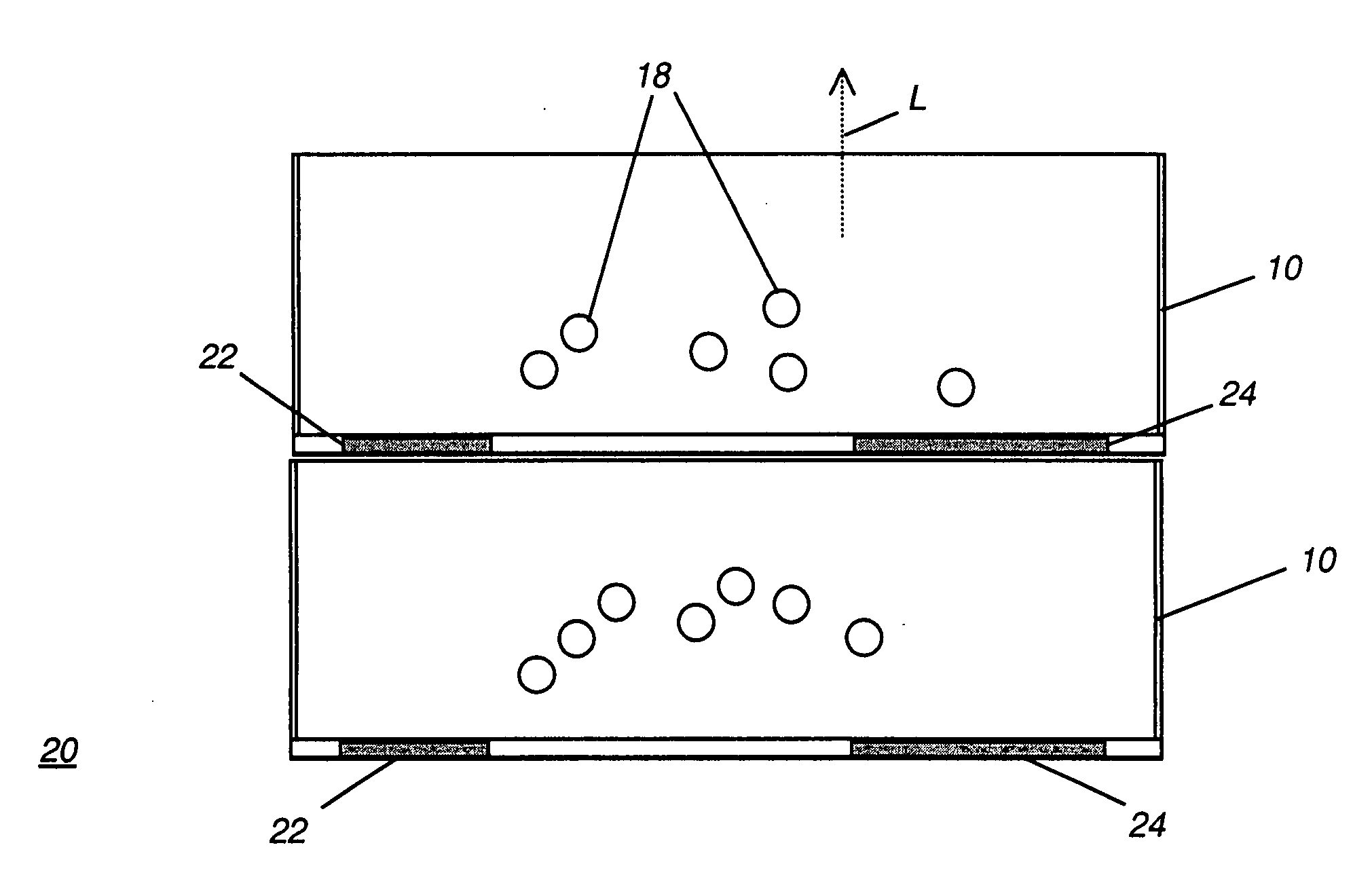
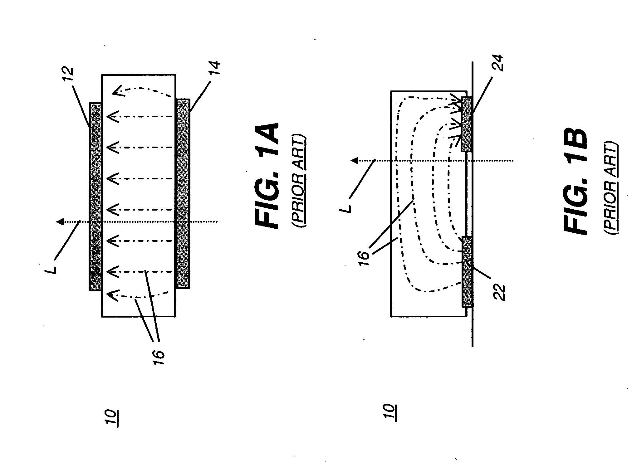
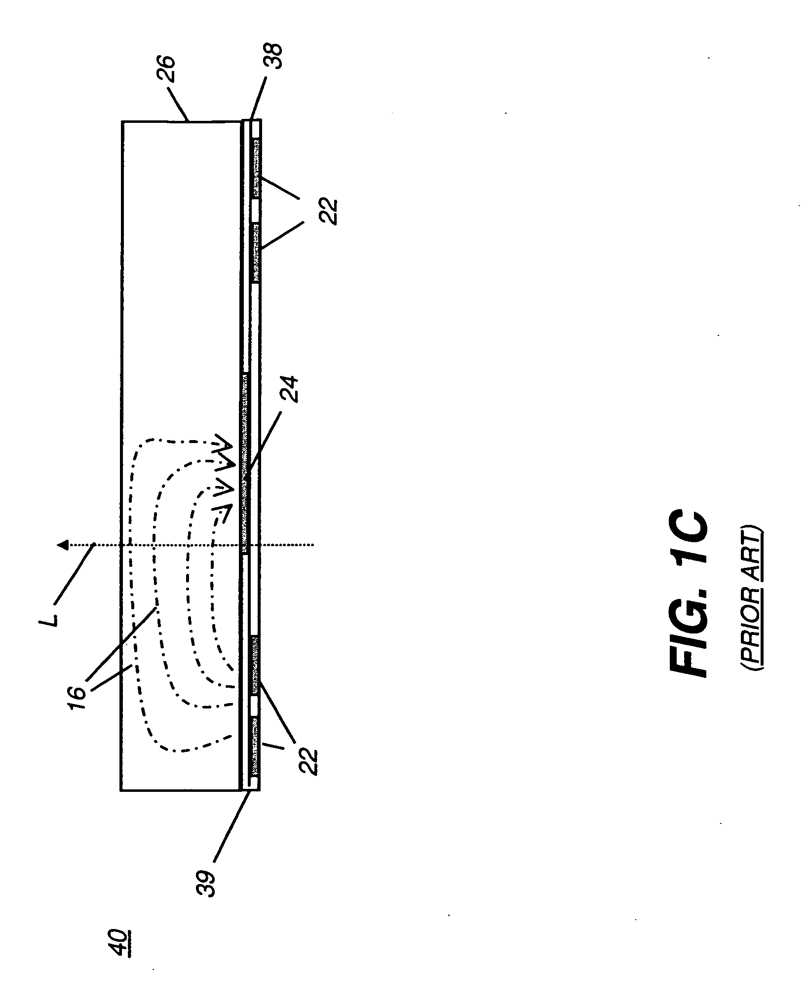
[0051] As indicated above, the present invention is directed to providing a stacked electro-optical cell having minimum electrical field crosstalk. The apparatus of the present invention compensates for crosstalk by using an electrical field isolation layer between two electro-optic cells in the stack.

[0052] The term electro-optic as it is applied to a material or to a display has its conventional meaning in the imaging arts, referring to modulation of a material having at least first and second display states that differ in at least one optical property. A state-changing mechanism causes an electro-optical material, such as an electro-optical imaging fluid, to change between its first and second display states according to application of an electrical field or electron transfer to the imaging material. Typically, the optical property is color perceptible to the human eye; however, some other optical property can also be affected, such as optical transmission, reflectance, luminesc...


PUM

PropertyMeasurementUnit
dielectric constantaaaaaaaaaa
diameteraaaaaaaaaa

Abstract

The present invention relates generally to the field of electro-optical modulating displays, for example, electrophoretic displays, and more particularly to a display having an array of stacked cells. In particular, the invention discloses the use of a electrical field isolation layer between the stacked arrays of microcells, , or alternative means, for reducing or eliminating cross-talk between the microcells in vertically adjacent layers of the stacked display.

Description

CROSS-REFERENCE TO RELATED APPLICATIONS [0001] The present application is related to U.S. application Ser. No. 10 / 953,623, filed Sep. 29, 2004, by Peter T. Aylward et al. and entitled, “Antistatic Layer for Electrically Modulated Display,” hereby incorporated by reference.FIELD OF THE INVENTION [0002] The present invention relates generally to the field of electro-optical modulating displays, for example, electrophoretic displays, and more particularly to a display having an array of stacked cells. BACKGROUND OF THE INVENTION [0003] The electrophoretic display is a type of electro-optic display that offers an electronic alternative to conventional printed paper media for many applications. Based on the electrophoresis phenomenon of charged pigment particles suspended in a solvent, the electrophoretic display is non-emissive, unlike conventional electronically modulated surfaces such as cathode ray displays or Organic Light Emitting Diode (OLED) displays. Unlike other types of sheet ...

Claims


Application Information

Patent Timeline
Patent Type & Authority Applications(United States)
IPC IPC(8): G02B26/00G02F1/167
CPCG02F1/134363G02F1/1347G02F2201/16G02F2001/133334G02F1/167G02F1/133334
Inventor AYLWARD, PETER T.ROBINSON, KELLY S.NG, KAM C.BREWER, JOHN C.
Owner EASTMAN KODAK CO
Why Eureka
Try Eureka