
Method of determining lens materials for a projection exposure apparatus

a technology of exposure apparatus and lens material, which is applied in the direction of mountings, magnification glasses, instruments, etc., can solve the problems of increasing the heating of the lens, reducing the brightness of the image, and the conventional lens material such as quartz glasses is not sufficiently transparent in the deep ultraviolet wavelength domain, so as to reduce the quantity of expensive fluoride crystals and achieve the effect of optimizing the use of fluoride crystals, reducing aberrations, and reducing the quantity of expensive flu

Inactive Publication Date: 2007-08-23
CARL ZEISS SMT GMBH
View PDF99 Cites 18 Cited by
  • Summary
  • Abstract
  • Description
  • Claims
  • Application Information

AI Technical Summary

Benefits of technology

[0017] Often the design objective is not (or not exclusively) the reduction of overall retardance, but to positively affect the retardance or its angular pupil distribution for achieving other advantageous effects. For example, in many cases it is more desirable to have a particular symmetric angular retardance distribution than to achieve a minimum mean retardance. Therefore the optimum crystal lattice orientations depend on the specific design objective.
[0018] Unfortunately, the path lengths and directions of the rays through the lenses cannot be varied just at it would be required for achieving the desired retardance property. This is because the shape of the lenses, their arrangement within the optical system and thus also the optical paths taken by light rays when propagating through the lenses are almost completely determined by the design of the optical system as a whole in view of the imaging properties that are to be achieved.
[0019] Until now, more or less heuristic approaches have been followed when it was to determine which lenses should be made of a fluoride crystal and, if there are any such lenses, which measures can be taken in order to achieve tolerable aberrations caused by intrinsic birefringence. SUMMARY OF THE INVENTION
[0020] It is a first object of the present invention to provide a design method that allows to reduce the quantity of expensive fluoride crystals needed as lens material without accepting intolerable aberrations.
[0021] It is a further object of the present invention to provide a design method that allows to optimize the use of fluoride crystals if the number of available crystals is limited for cost or other reasons.
[0022] The first object is achieved by a method comprising the steps of:

Problems solved by technology

One of the major problems encountered when using exposure light having such short wavelengths is the fact that conventional lens materials such as quartz glasses are not sufficiently transparent in the deep ultraviolet wavelength domain.
A low transparency reduces the brightness of the image and results in increased heating of the lenses.
Lens heating, in turn, often causes undesired variations of the shape of the lenses and also of their index of refraction.
When light passes through a unit length of a birefringent material, the difference in refractive index for the two ray paths will result in an optical path difference or retardance.
These aberrations are capable of significantly degrading image resolution and introducing distortion of the image.
Unfortunately, the path lengths and directions of the rays through the lenses cannot be varied just at it would be required for achieving the desired retardance property.

Method used


Image

  • Method of determining lens materials for a projection exposure apparatus
  • Method of determining lens materials for a projection exposure apparatus
  • Method of determining lens materials for a projection exposure apparatus

Examples


first embodiment

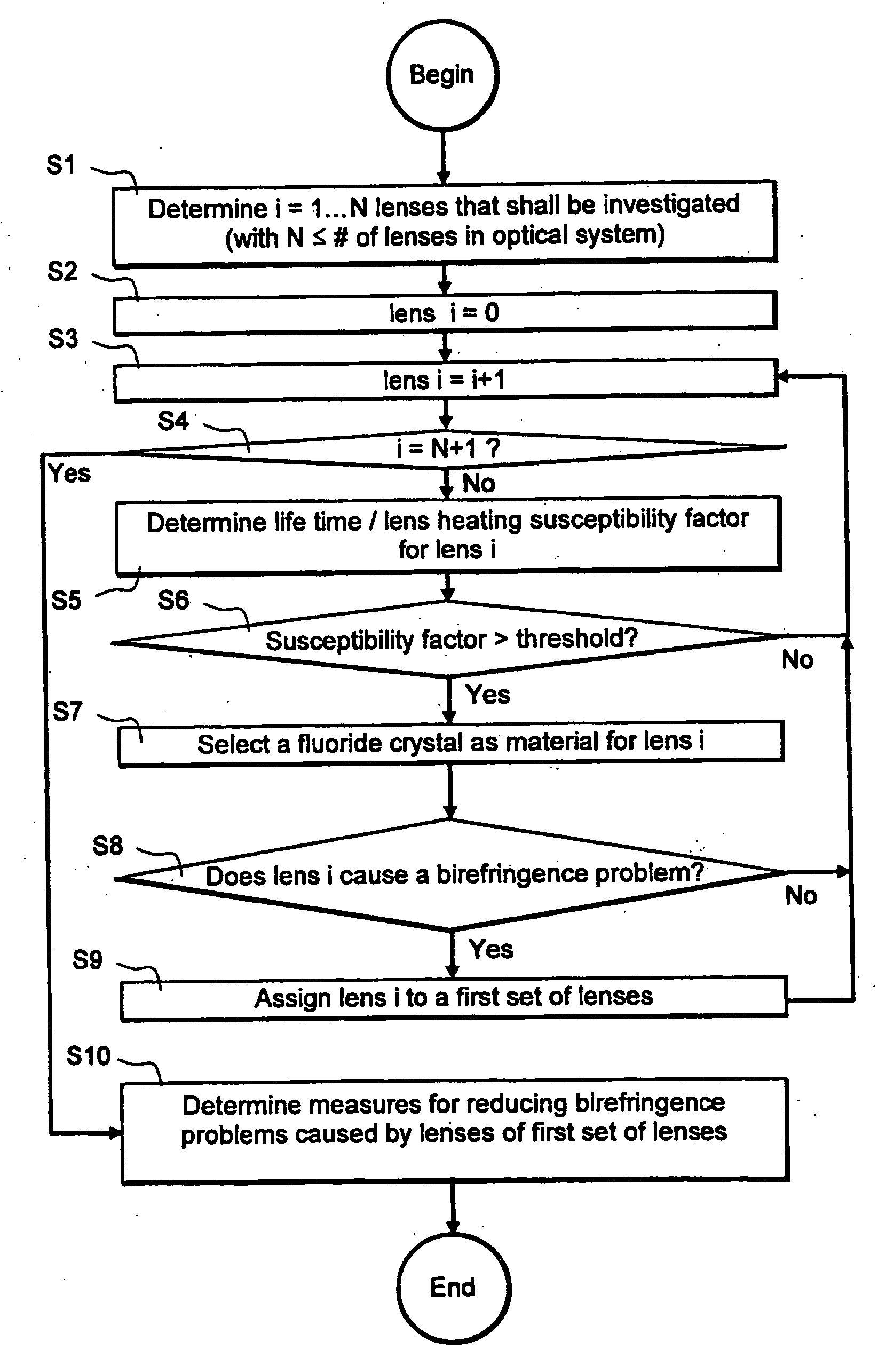
[0152] In the projection objective 10′, the threshold value for the lifetime / lens heating susceptibility factor KLT / LH has been determined to be 5. This means that all lenses with

KLT / LH>5  (13)

are significantly susceptible to deteriorations due to lifetime and / or lens heating effects and consequently should be made of a fluoride crystal such as CaF2. With this determination of the threshold value for the lifetime / lens heating susceptibility factor KLT / LH, a fluoride crystal, here CaF2, should be selected according to step S7 only for the last lens L20′.

[0153] The lens L20′ has a very large geometrical birefringence factor KgIB of more than 52.4 and thus causes significant birefringence. Therefore it is necessary to compensate for the birefringence caused by the lens L20′.

[0154] The most promising approach to compensate this birefringence is to split up the lens L20′ into two lens parts rotated around the optical axis. If a (100) crystal material is selected, a relative rotation ...

second embodiment

[0157] In the projection objective 10′, the threshold value for the lifetime / lens heating susceptibility factor KLT / LH has been determined to be 1.8. This means that all lenses with

KLT / LH>1.8  (13)

are significantly susceptible to deterioration due to lifetime and / or lens heating effects and consequently should be made of a fluoride crystal such as CaF2. With this determination of the threshold value for the lifetime / lens heating susceptibility factor KLT / LH, a fluoride crystal, here CaF2, should be selected according to step S7 not only for the last lens L20′, but also for the lenses L10′ and L19′.

[0158] Since these lenses L10′ and L19′ are now, compared with the first embodiment shown in FIG. 10, made of a material having a different index of refraction, the design of the projection objective 10′ has to be slightly adjusted. Tables 7 and 8 contain the adjusted design specification of the projection objective 10′.

[0159] The most promising approach to compensate this birefringenc...

third embodiment

[0161] In the projection objective 10′, the threshold value for the lifetime / lens heating susceptibility factor KLT / LH is still 1.8 so that the last lens L20′ and the lenses L10′ and L19′ are made of a fluoride crystal material.

[0162] However, if the compensation achieved with three lenses L10′, L19′ and L20′ is considered to be insufficient (step S10-1), it may be envisioned to improve the compensation by selecting a fluoride crystal for an additional lens. L14′ is a good candidate for this selection because according to table 6, the lens L14′ has, in spite of its small lifetime / lens heating susceptibility factor KLT / LH of 0.8, a large geometrical birefringence factor KgIB=17.0 (see step S10-3).

[0163] A fourth lens made of a fluoride crystal material makes it possible to choose different compensation approaches. For example, the last two lenses L19′ and L20′ may be made of (111) crystals with their crystal lattices rotated around the optical axis by an angle of 60° or an uneven mu...


PUM


Abstract

A method of determining materials of lenses contained in an optical system of a projection exposure apparatus is described. First, for each lens of a plurality of the lenses, a susceptibility factor KLT / LH is determined. This factor is a measure of the susceptibility of the respective lens to deteriorations caused by at least one of lifetime effects and lens heating effects. Then a birefringent fluoride crystal is selected as a material for each lens for which the susceptibility factor KLT / LH is above a predetermined threshold. Theses lenses are assigned to a first set of lenses. For these lenses, measures are determined for reducing adverse effects caused by birefringence inherent to the fluoride crystals.

Description

CROSS-REFERENCE TO RELATED APPLICATIONS [0001] This application is a Continuation-in-Part of U.S. patent application Ser. No. 11 / 181,694, entitled “METHOD OF DETERMINING LENS MATERIALS FOR A PROJECTION EXPOSURE APPARATUS,” filed on Jul. 14, 2005, which claims priority of Provisional Patent Application No. 60 / 630,168, filed Nov. 22, 2004. This application is also a Continuation-in-Part of U.S. patent application Ser. No. 11 / 035,103, entitled “CATADIOPTRIC PROJECTION OBJECTIVE,” filed on Jan. 14, 2005, which claims priority of Provisional Patent Application No. 60 / 536,248, filed on Jan. 14, 2004; Provisional Patent Application No. 60 / 587,504, filed on Jul. 14, 2004, Provisional Patent Application No. 60 / 591,775, filed on Jul. 27, 2004; Provisional Patent Application No. 60 / 612,823; filed on Sep. 24, 2004; and Provisional Patent Application No. 60 / 617,674, filed on Oct. 13, 2004. The contents of the above-mentioned U.S. Patent Applications and Provisional Patent Applications are incorp...

Claims


Application Information

Patent Timeline
IPC IPC(8): G02B3/00
CPCG02B1/02G02B17/08G03F7/70975G03F7/70225G03F7/70966G02B27/0012
Inventor KAMENOV, VLADIMIRKRAEHMER, DANIELTOTZECK, MICHAELGRUNER, TORALFDODOC, AURELIANSHAFER, DAVIDULRICH, WILHELMBUENAU, RUDOLF VONMANN, HANS-JUERGENEPPLE, ALEXANDER
Owner CARL ZEISS SMT GMBH
Learn More