Motor drive semiconductor integrated circuit and magnetic disk storage apparatus

a technology of integrated circuits and motors, applied in the direction of electric controllers, instruments, maintaining head carrier alignment, etc., can solve the problems of high design load, difficult switching control, and increase in circuit scale, and achieve high-precision driving control

Inactive Publication Date: 2007-08-23
KOKAMI YASUHIKO
View PDF6 Cites 14 Cited by
  • Summary
  • Abstract
  • Description
  • Claims
  • Application Information

AI Technical Summary

Benefits of technology

[0013] It is another object of the invention to provide a motor drive semiconductor integrated circuit of a voice coil motor that can make high precision current detection for feedback control of the voice coil motor without being affected by jitter of a sampling clock and without depending on a PWM cycle.
[0048] Namely, the invention can acquire a drive control semiconductor integrated circuit for a coil motor capable of executing high precision driving control.

Problems solved by technology

In the system that switches PWM driving to linear driving at the shift of the seek operation to the track follow operation, however, switching must be conducted smoothly and quickly but precision switching control is difficult.
Because a control circuit for PWM driving and a control circuit for linear driving must be designed separately and optimally, a design load becomes great and the circuit scale increases.
Nonetheless, it is relatively difficult to fabricate the D / A conversion circuit having 16 or more bits by a CMOS process that is predominant in existing semiconductor fabrication technologies.
A system that detects a voltage occurring across both ends of a resistor connected in series with a coil has generally been employed in the past as a current detection system for the feedback control of the voice coil motor but it has been clarified that this system involves various problems such as a voltage loss in the sense resistor and a detection error resulting from jitter of a sampling clock.

Method used


Image

  • Motor drive semiconductor integrated circuit and magnetic disk storage apparatus
  • Motor drive semiconductor integrated circuit and magnetic disk storage apparatus
  • Motor drive semiconductor integrated circuit and magnetic disk storage apparatus

Examples


Embodiment Construction

[0071] Preferred embodiments of the invention will be hereinafter explained with reference to the accompanying drawings.

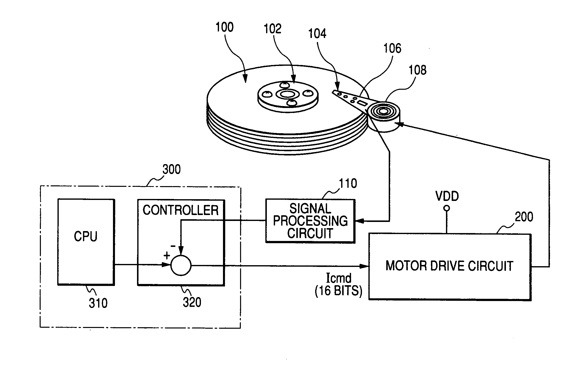
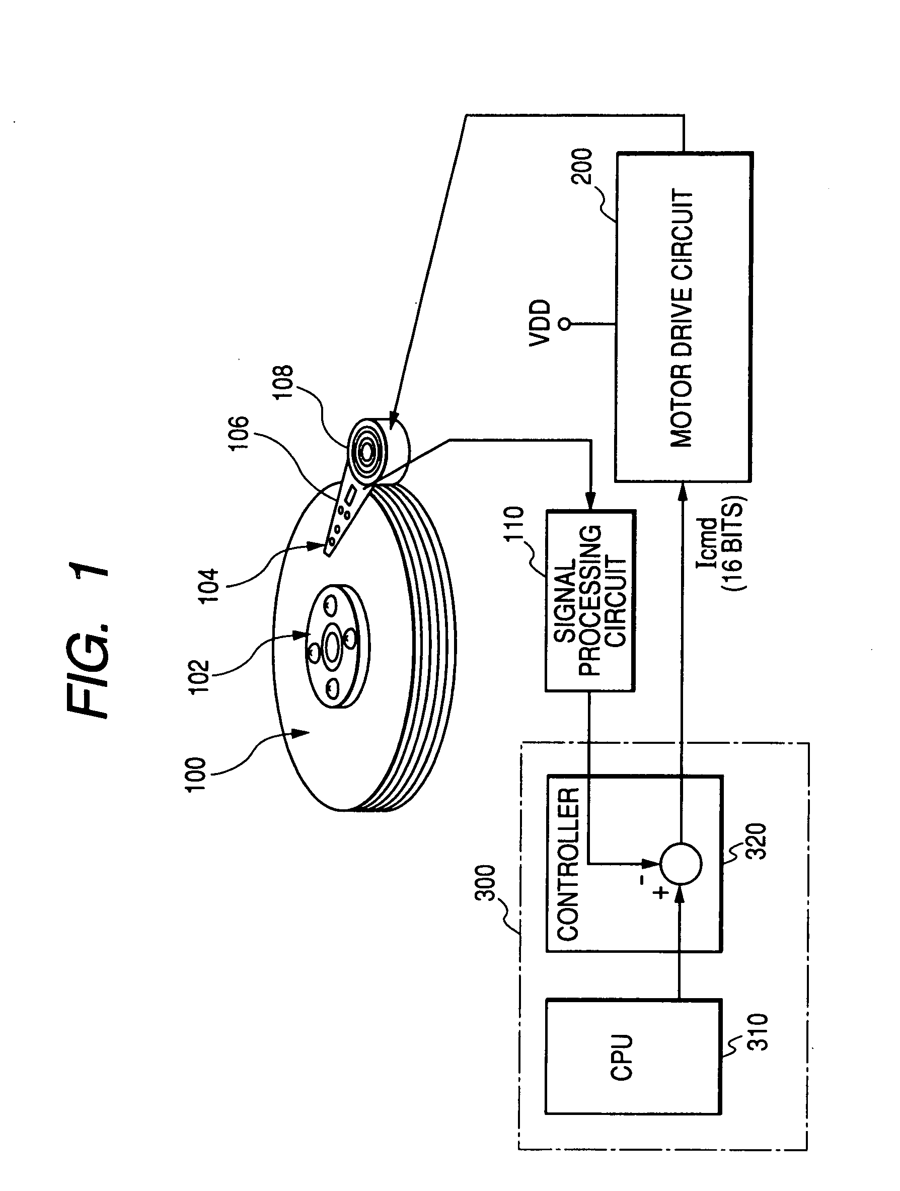
[0072]FIG. 1 shows an outline of a magnetic disk storage apparatus to which the technology of the invention is applied.

[0073] The magnetic disk storage apparatus shown in the drawing includes a magnetic disk 100, a spindle motor 102 for driving and rotating the magnetic disk 100, a magnetic head (inclusive of a write magnetic head and a read magnetic head) 104 for executing read / write of information to and from a storage track on the magnetic disk 100, an arm 106 having the magnetic head 104 at its distal end, a voice coil motor 108 for rotating the arm 106 and moving the magnetic head 104 in a radial direction over the disk 100, a motor drive circuit 200 for driving the voice coil motor 108, a signal processing circuit (signal processing IC) 110 for reading position information from the read signal of the magnetic head 104 and a control portion 300 for sending a...


PUM

PropertyMeasurementUnit
frequencyaaaaaaaaaa
frequencyaaaaaaaaaa
currentaaaaaaaaaa

Abstract

The invention provides a motor drive semiconductor integrated circuit for driving and controlling a voice coil motor that can conduct a seek operation, a track follow operation and a settling operation through PWM control, has desired control accuracy and can be produced by a CMOS process. In a voice coil motor drive circuit for executing positioning control of a magnetic head by feedback-controlling a driving current of a voice coil motor for moving a magnetic head over a magnetic disk for reading information from a storage track on the magnetic disk driven for rotation while a read state of the magnetic head is being monitored, head movement control such as a seek operation, a track follow operation etc, of the magnetic head is executed by PWM driving on the basis of a command value from a controller.

Description

CROSS-REFERENCE TO RELATED APPLICATION [0001] The present application is a continuation of application Ser. No. 11 / 098,644, filed Apr. 5, 2005, which claims priority from Japanese patent application No. 2004-111817, filed on Apr. 6, 2004, the content of which is hereby incorporated by reference into this application.BACKGROUND OF THE INVENTION [0002] 1. Field of the Invention [0003] This invention relates to a control technology of a magnetic disk storage apparatus and further to a control technology of a voice coil motor for moving a magnetic head for conducting read / write of information from and to a storage track on a magnetic storage disk that is driven and rotated. [0004] 2. Description of the Related Art [0005] A magnetic disk storage apparatus includes a magnetic head for executing read / write of information to and from a storage track on a magnetic storage disk driven and rotated, a voice coil motor for moving the magnetic head on the disk and a voice coil motor drive control...

Claims


Application Information

Patent Timeline
Patent Type & Authority Applications(United States)
IPC IPC(8): G11B5/596G05B11/28G11B21/10G11B21/08G11B25/04G11B33/12H02P25/034H02P25/06
CPCG05B11/28G11B33/121G11B25/043G11B5/5547
Inventor KOKAMI, YASUHIKO
Owner KOKAMI YASUHIKO
Why Eureka
Try Eureka