Processor, multiprocessor system, processor system, information processing apparatus, and temperature control method

a multi-processor system and temperature control technology, applied in the field of processor technology, can solve the problems of inability to avoid “hot spot”, abnormally high temperature of the chip, and improper operation of the chip, so as to prevent mal-operation, control the heat value generated by the processor, and avoid the effect of deteriorating the performance of the processor

Inactive Publication Date: 2007-08-23
SONY COMPUTER ENTERTAINMENT INC
View PDF10 Cites 50 Cited by
  • Summary
  • Abstract
  • Description
  • Claims
  • Application Information

AI Technical Summary

Benefits of technology

[0018] According to the present invention, heat value generated from the processor is contro

Problems solved by technology

As a chip is heated to a high temperature, the chip may operate improperly or the long-term reliability thereof decreases.
Since the distribution of power consumption on a chip is not uniform, the problem of “hot spot”, a part of the chip at an abnormally high temperature, cannot be avoided.
As such, time response is poor.
Unless heat is radiated i

Method used


Image

  • Processor, multiprocessor system, processor system, information processing apparatus, and temperature control method
  • Processor, multiprocessor system, processor system, information processing apparatus, and temperature control method
  • Processor, multiprocessor system, processor system, information processing apparatus, and temperature control method

Examples


first embodiment

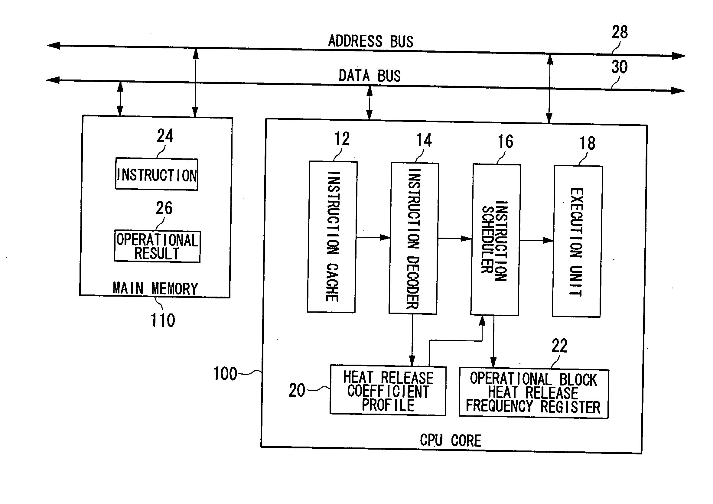
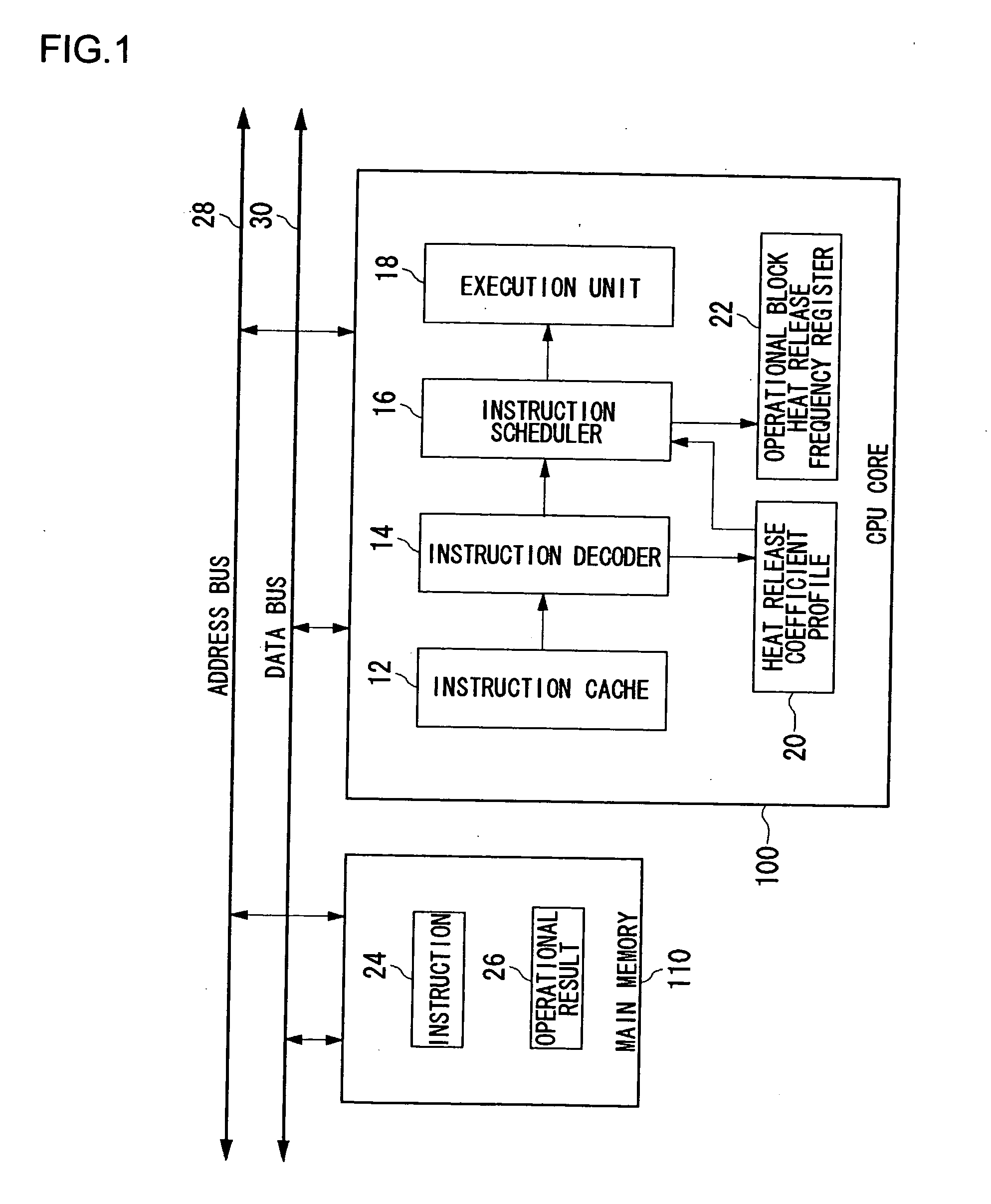
[0025]FIG. 1 illustrates the structure of a processor system according to a first embodiment of the present invention. The processor system includes a CPU core 100 and a main memory 110 which are connected to an address bus 28 and a data bus 30. The CPU core 100 designates an address in the main memory 110 and reads and writes data in the main memory 110. The CPU core 100 includes an instruction cache 12, an instruction decoder 14, an instruction scheduler 16, an execution unit 18, a heat release coefficient profile 20 and an operational block heat release coefficient register 22. The main memory 110 stores an instruction 24 and an operational result 26.

[0026] The instruction 24 read by the CPU core 100 from the main memory 110 is cached in the instruction cache 12. The instruction decoder 14 sequentially decodes the instruction 24 cached in the instruction cache 12 and supplies the decoded instruction to the instruction scheduler 16. The instruction scheduler 16 schedules the inst...

second embodiment

[0050]FIG. 6 illustrates the structure of a processor system according to a second example of the present invention. The processor system according to the second embodiment is a multiprocessor system including two subprocessors 230a and 230b connected to a bus, in addition to a main processor 200 corresponding to the CPU core 100 of the first embodiment. The main processor 200 accesses a DRAM 220 via the bus and reads data therefrom. The main processor 200 caches the data in the cache 210. The main processor 200 allocates tasks to the two sub-processors 230a and 230b as appropriate for execution of a program.

[0051] The main processor 200 includes various functional blocks of the CPU core 100 described in the first embodiment including the instruction cache 12, the instruction decoder 14, the instruction scheduler 16, the instruction unit 18, the heat release coefficient profile 20, the operational block heat release frequency register 22, the heat release frequency adder 32, the he...


PUM


Abstract

An instruction decoder identifies, for each instruction, an operational block involved in the execution of the instruction and an associated heat release coefficient. The instruction decoder stores identified information in a heat release coefficient profile. An instruction scheduler schedules the instructions in accordance with the dependence of the instructions on data. A heat release frequency adder cumulatively adds the heat release coefficient to the heat release frequency of the operational block held in the operational block heat release frequency register as the execution of the scheduled instructions proceeds. A heat release frequency subtractor subtracts from the heat release frequency of the operational blocks in the operational block heat release frequency register in accordance with heat discharge that occurs with time. A hot spot detector detects an operational block with its heat release frequency, held in the operational block heat release frequency register, exceeding a predetermined threshold value as a hot spot. The instruction scheduler delays the execution of the instruction involving for its execution the operational block identified as a hot spot.

Description

TECHNICAL FIELD [0001] The present invention relates to a processor technology and, more particularly, to a processor, a multiprocessor system, a processor system, an information processing apparatus and a temperature control method capable of controlling heat value. BACKGROUND TECHNOLOGY [0002] As the process of fabrication becomes increasingly finer and components are more highly integrated, heat value has become an important concern in designing an LSI as a parameter indicating a limit of chip performance. As a chip is heated to a high temperature, the chip may operate improperly or the long-term reliability thereof decreases. Therefore, various countermeasures for heat release are taken. For example, a radiator fin may be provided on top of the chip to allow heat from the chip to escape. [0003] Since the distribution of power consumption on a chip is not uniform, the problem of “hot spot”, a part of the chip at an abnormally high temperature, cannot be avoided. Accordingly, a st...

Claims


Application Information

Patent Timeline
IPC IPC(8): G05D23/00G06F9/32G06F1/00G06F1/20G06F1/32G06F9/30G06F9/38G06F9/46G06F9/50G06F15/177
CPCG06F1/206G06F1/3203G06F1/329G06F9/3836Y02B60/144G06F9/4881G06F9/505Y02B60/1217G06F9/3869Y02D10/00G06F1/00G06F9/30G06F9/46G06F9/50
Inventor ADACHI, KENICHIYAZAWA, KAZUAKITAKIGUCHI, IWAOIMAI, ATSUHIKOTAMURA, TETSUJI
Owner SONY COMPUTER ENTERTAINMENT INC
Why Eureka
Try Eureka