Liquid cooling loops for server applications

a server application and cooling loop technology, applied in the direction of lighting and heating apparatus, electrical apparatus casings/cabinets/drawers, furniture parts, etc., can solve the problems of high thermal density, insufficient cooling chips in conventional cooling with heat pipes and fan mounted heat sinks, and significant challenges in high-performance integrated circuit cooling. , to achieve the effect of increasing surface area and low thermal resistan

Active Publication Date: 2007-08-30
LIEBERT
View PDF99 Cites 83 Cited by
  • Summary
  • Abstract
  • Description
  • Claims
  • Application Information

AI Technical Summary

Benefits of technology

[0011] Fundamental to the operation of the independent cooling loops system described above is the thermal interface formed between the rejector plate of the electronics server and the chassis cold plate of the server rack. These cooling systems provide mechanisms and form factors for bringing a heat exchanger from the rack into thermal contact with a heat exchanger from the electronics server. For low thermal resistance, a thermal interface material (TIM), such as thermal grease or a thermal pad, may be used. To ensure good thermal contact, pressure is applied between the two heat exchangers, the rejector plate and the chassis cold plate. Methods for applying pressure include, but are not limited to, mechanical clamping, springs, electro-mechanical motors or actuators, pneumatics and hydraulics. The heat exchangers can take a variety of shapes, including planar, cylindrical, curvilinear, or other non-planar configurations. The mating surfaces of the heat exchangers can be smooth or with physical features such as mating teeth to increase surface area or ensure alignment. Thermal contact can be made on one or more surfaces creating a sandwich type structure. A heat exchanger can be a single solid piece or can be made up of an array of smaller heat exchangers to allow flexibility when mating curved to curved surfaces.

Problems solved by technology

Cooling of high performance integrated circuits with high heat dissipation is presenting significant challenge in the electronics cooling arena.
Conventional cooling with heat pipes and fan mounted heat sinks are not adequate for cooling chips with every increasing wattage requirements, including those exceeding 100 W.
However, the high density of integrated circuits also leads to high thermal density, which is beyond the capability of conventional air-cooling methods.
A particular problem with cooling integrated circuits on electronics servers is that multiple electronics servers are typically mounted in close quarters within a server chassis.
In such configurations, electronics servers are separated by a limited amount of space, thereby reducing the dimensions within which to provide an adequate cooling solution.
Typically, stacking of electronics servers does not provide the mounting of large fans and heat sinks for each electronics server.
However, considering the limited free space surrounding the stacked electronics servers within the server chassis, the amount of air available for cooling the integrated circuits is limited.
As servers increase in power and power density, it is no longer feasible to air cool the entire server rack.
Due to the density of the electronics and the high power densities of ultra high performance servers, the heat picked up by a liquid cooling loop cannot be effectively discharged to the air via a radiator, as is common practice in other form factors such as desktops and work stations.

Method used


Image

  • Liquid cooling loops for server applications
  • Liquid cooling loops for server applications
  • Liquid cooling loops for server applications

Examples


first embodiment

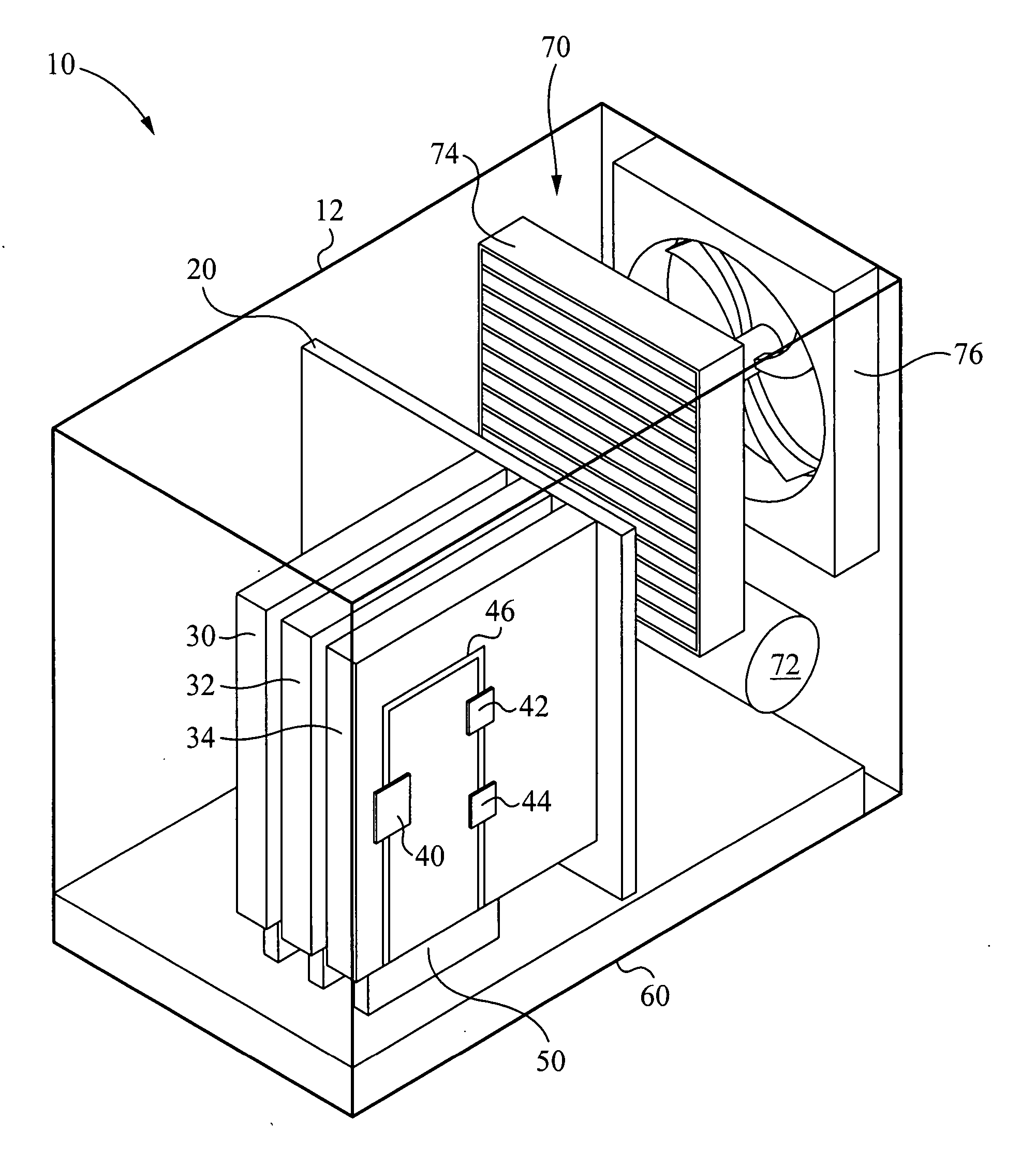
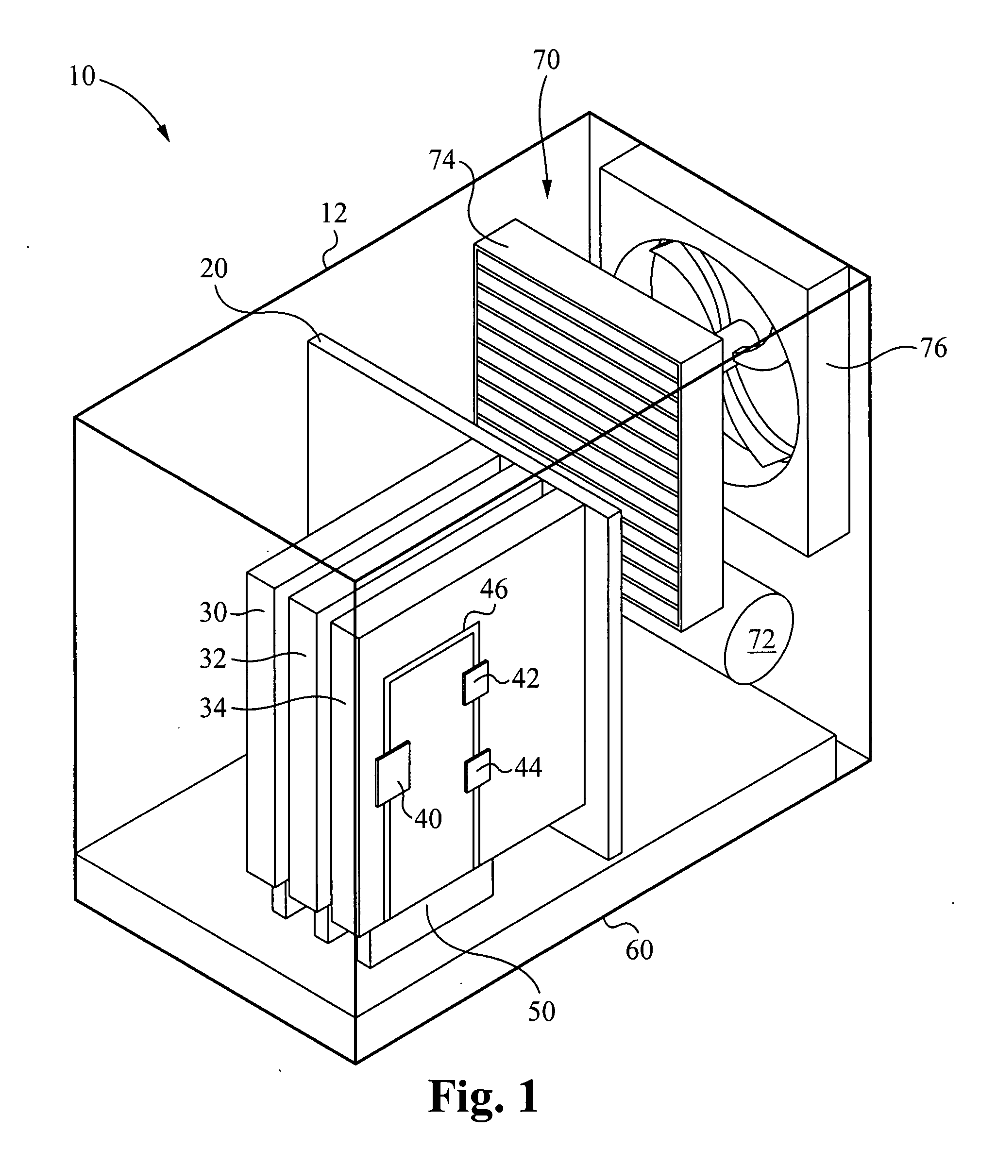
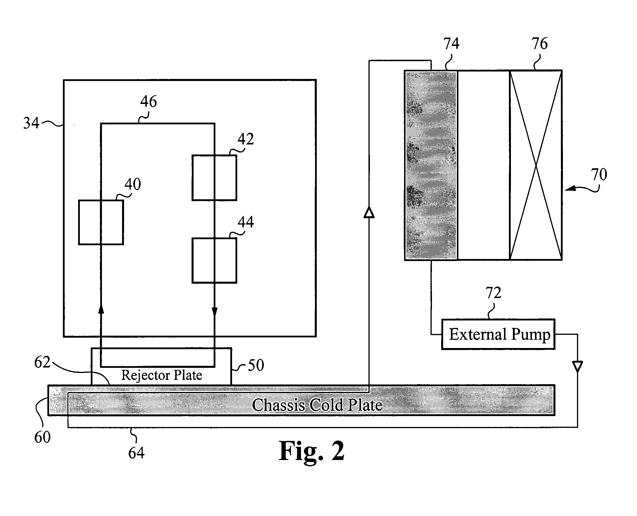
[0045] In a first embodiment, the liquid based cooling system for each electronics server includes a rejector plate. The fluid lines coupling the MCPs and the server pump are also coupled to the rejector plate with fluid channels configured therein. The MCPs, the server pump, the rejector plate, and the fluid lines connected thereto form a first closed loop. Each server chassis includes at least one chassis cold plate. The rejector plate is coupled to the chassis cold plate via a thermal interface material. The rejector plates for each of the electronics servers are coupled to the chassis cold plate in this manner such that all rejector plates, and therefore the cooling system for each electronics server, are coupled to the chassis cold plate. Each electronics server is installed into a backplane along an insertion vector. The thermal interface between the rejector plate of the electronics server and the chassis cold plate is formed along a non-perpendicular plane relative to the in...

second embodiment

[0061]FIG. 3 illustrates a side view of an exemplary cooling system according to the present invention. The cooling system 110 can be identical to the cooling system 10 of FIG. 1 with the exception that the liquid-to-air heat exchanging system 70 (FIG. 1) of cooling system 10 is replaced by an external water supply 170. The external water supply 170 represents a continuous running water supply, such as the public water supply provided to most commercial and residential facilities. Alternatively, the external water supply 170 represents an external source of any type of fluid to which heat is transferred. In operation of the cooling system 110, fresh water from the external water supply 170 flows to the chassis cold plate 60. Heat from the chassis cold plate 60 is transferred to the water in the same manner as that described in relation to cooling system 10 (FIG. 1). The heated water flows from the chassis cold plate 60 to the external water supply 170, where the heated water is disp...

third embodiment

[0063]FIG. 5 illustrates a side view of an exemplary cooling system 210 according to the present invention. Although cooling system 210 is shown in FIG. 5 as including only a single electronics server 134, it is understood that the cooling system 210 also includes a chassis housing (not shown) and a back plane (not shown) configured to hold up to N electronics servers in a manner similar to that described in relation to cooling system 10 in FIG. 1. For purposes of discussion, each electronics server within the cooling system 210 is described as including two processors. It is again understood that each electronics server in the cooling system 210 can be configured independently and that each electronics server can include more or less than two heat generating devices, such as processors.

[0064] A liquid based cooling system is coupled to the electronics server 134. The liquid based cooling system includes an MCP 142 and an MCP 144 coupled together via one or more fluid lines 146. The...


PUM


Abstract

A mounting system provides mechanisms and form factors for bringing a heat exchanger from a server rack into thermal contact with a heat exchanger from a electronics server. To ensure good thermal contact, pressure is applied between the two heat exchangers, the rejector plate and the chassis cold plate. The mounting mechanism used to engage and disengage the heat exchangers is configured to isolate the force applied to the two heat exchangers. The mounting mechanism includes an interlocking mechanism that prevents transfer of the applied force to the rest of the electronics server. Without isolating this force, the force is applied to the electronics server and/or the rack chassis, possibly disconnecting the electrical connections between the electronics server and the rack, as well as providing mechanical stress to the electronics server and the rack chassis. The mounting mechanism is also coupled to the electronics server locking mechanism such that the action of locking the electronics server into the rack causes the heat exchangers to engage in thermal contact. This is a fail safe procedure since no separate process is required to engage the electronics server cooling loop.

Description

RELATED APPLICATIONS [0001] This application claims priority of U.S. provisional application, Ser. No. 60 / 774,764, filed Feb. 16, 2006, and entitled “Thermal Interconnect”, by these same inventors. This application incorporates U.S. provisional application, Ser. No. 60 / 774,764 in its entirety by reference.FIELD OF THE INVENTION [0002] The invention relates to a mounting mechanism in general, and specifically, to a mounting mechanism to form a thermal interface between two heat exchanging devices. BACKGROUND OF THE INVENTION [0003] Cooling of high performance integrated circuits with high heat dissipation is presenting significant challenge in the electronics cooling arena. Conventional cooling with heat pipes and fan mounted heat sinks are not adequate for cooling chips with every increasing wattage requirements, including those exceeding 100 W. [0004] Electronics servers, such as blade servers and rack servers, are being used in increasing numbers due to the higher processor perfor...

Claims


Application Information

Patent Timeline
Patent Type & Authority Applications(United States)
IPC IPC(8): H05K7/20
CPCH05K7/20727H05K7/20772H05K7/20781H01L2924/0002H01L2924/00
Inventor CHOW, NORMANTSAO, PAULWERNER, DOUGLAS E.MCMASTER, MARKUPADHYA, GIRISHLANDRY, FREDERICSPEARING, IANSCHRADER, TIM
Owner LIEBERT
Why Eureka
Try Eureka