
Longitudinally pumped solid state laser and methods of making and using

a laser and solid state technology, applied in the direction of laser details, optical resonator shape and construction, electrical equipment, etc., can solve the problems of high cost, limited power scale up, and high reliability

Active Publication Date: 2007-08-30
CONTINUUM ELECTRO OPTICS
View PDF15 Cites 29 Cited by
  • Summary
  • Abstract
  • Description
  • Claims
  • Application Information

AI Technical Summary

Benefits of technology

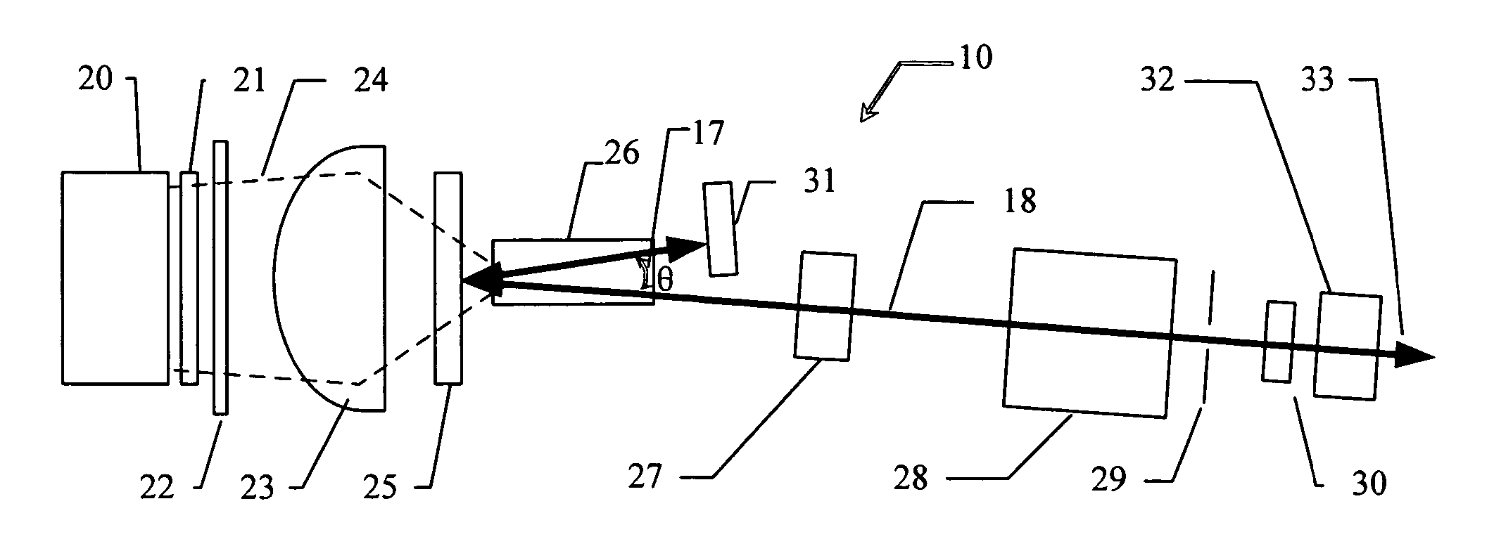
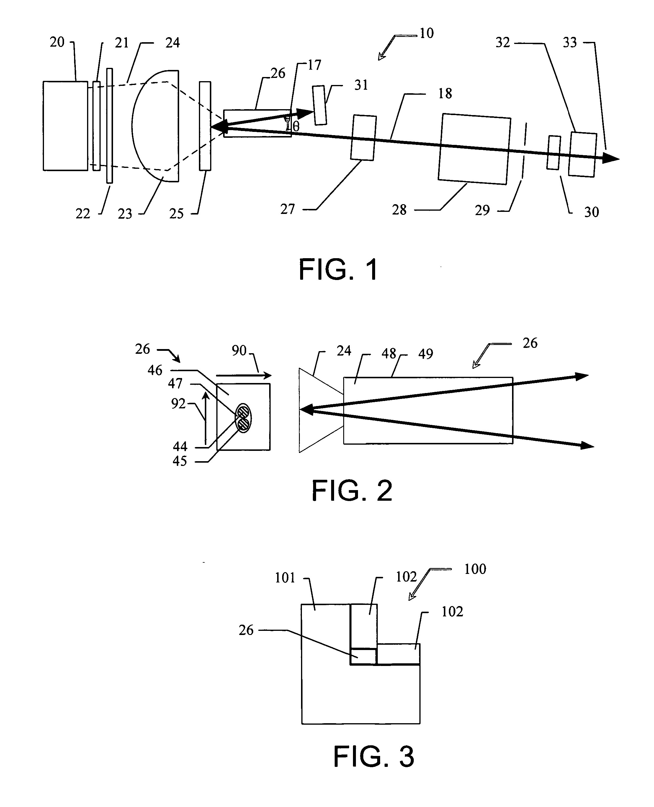
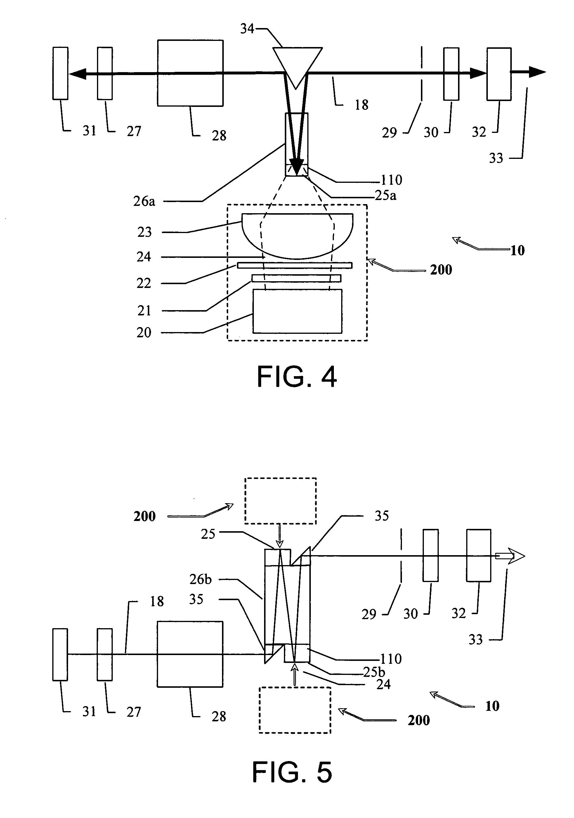
[0009] Yet another embodiment is a laser cavity including a gain medium; a first reflector; a second reflector; and an output coupler. The first reflector is substantially reflective to a laser light beam and substantially transmissive to a pump light beam and is spaced apart from a gain portion of the first gain medium. The first and second reflectors and the output coupler define a folded beam path having a first p

Problems solved by technology

Such schemes have shortcomings such as complexity, reliability (pointing and damage), limitations on power scale up, and higher cost.
For this reason, mode matching can be poor compared to end pumping and can result in low efficiency (typically 15 to 30%).
First, there is system complexity: at the diode laser input side, beam shaping and coupling optics are needed, while at the pumping side, a collimator and focusing optics are needed.
Second, loss from the fiber coupling and delivery system is typically 25% or more.
Fourth, optical damage at the fiber input surface, or mechanical damage due to over bending, twisting or other stress, can cause problems.
Fifth, optical damage of the gain medium can produce a limit for pump power scale up at each end of the gain medium.

Method used


Image

  • Longitudinally pumped solid state laser and methods of making and using
  • Longitudinally pumped solid state laser and methods of making and using
  • Longitudinally pumped solid state laser and methods of making and using

Examples


Embodiment Construction

[0026] The invention is directed to longitudinally pumped solid-state lasers and methods of making and using the lasers. In addition, the invention is directed to lasers that efficiently generate a high power, linearly polarized, and circularly symmetrical output laser beam and methods of making and using the lasers.

[0027] A laser apparatus can include an end pumping (longitudinally pumped) scheme using a folded resonator design with a V-shaped path through the pumped gain medium. In at least some embodiments, this design has one or more advantages such as high efficiency, reliability, good mode matching, and / or good gain guiding. In at least some embodiments, the design can also include compensation for one or both of gain and thermal asymmetry. Such compensation can include, for example, flipping the right and left sides of the laser beam by the folding reflection. Other potential advantages of at least some embodiments include better power scale-up, high damage threshold, and / or...


PUM


Abstract

A laser apparatus for producing a laser light beam can include a gain medium; a pump light source to provide a pump light beam to the gain medium; a first reflector disposed between the first gain medium and the first pump light source and spaced apart from a gain portion of the first gain medium; a second reflector; and an output coupler. The first reflector is substantially reflective to the laser light beam and substantially transmissive to the pump light beam. The first and second reflectors and the output coupler define a folded beam path having a first portion and a second portion. The first portion of the beam path extends from the first reflector to the second reflector through the gain medium and the second portion of the beam path extends from the first reflector to the output coupler through the gain medium. The first and second beam paths define, within the gain medium, a non-zero folding angle. Optionally, the laser apparatus can include a second pump light source that can pump the same, or a second, gain medium.

Description

FIELD [0001] The invention is directed to longitudinally pumped solid-state lasers and methods of making and using the lasers. In addition, the invention is directed to lasers that efficiently generate a high power, linearly polarized, and circularly symmetrical output laser beam and methods of making and using the lasers. BACKGROUND [0002] High power, diode laser pumped, solid-state lasers have many potential applications, for example, ceramic or silicon wafer scribing and drilling; diamond cutting and scribing; and laser marking and engraving. Examples of such lasers include TEMoo or low-order-mode (LOM) devices with either continuous wave (CW) or Q-switched output at, for example, 1 μm or at the 2nd, 3rd or 4th harmonic wavelength. [0003] With the rapid development of diode-pumped solid-state lasers during the past two decades, a number of approaches have been investigated with the goal of increasing the overall efficiency of such devices. Pumping schemes using high power fiber c...

Claims


Application Information

Patent Timeline
IPC IPC(8): H01S3/093H01S3/081
CPCH01S3/025H01S3/0405H01S3/042H01S3/0606H01S3/235H01S3/081H01S3/0815H01S3/09415H01S3/117H01S3/0612
Inventor ZHANG, JIANSONG, JIEGUO, BOLIU, KUO-CHING
Owner CONTINUUM ELECTRO OPTICS
Learn More