Data transmission apparatus, data transmission method

Inactive Publication Date: 2007-08-30
PANASONIC CORP
View PDF2 Cites 9 Cited by
  • Summary
  • Abstract
  • Description
  • Claims
  • Application Information

AI Technical Summary

Benefits of technology

[0012] Therefore, an object of the present invention is to provide a data communication apparatus which causes th

Problems solved by technology

Particularly, improvement in processing speed of a computer has been remarkable in recent years, and thus there has been a problem in that if a new computer base

Method used


Image

  • Data transmission apparatus, data transmission method
  • Data transmission apparatus, data transmission method
  • Data transmission apparatus, data transmission method

Examples


first embodiment

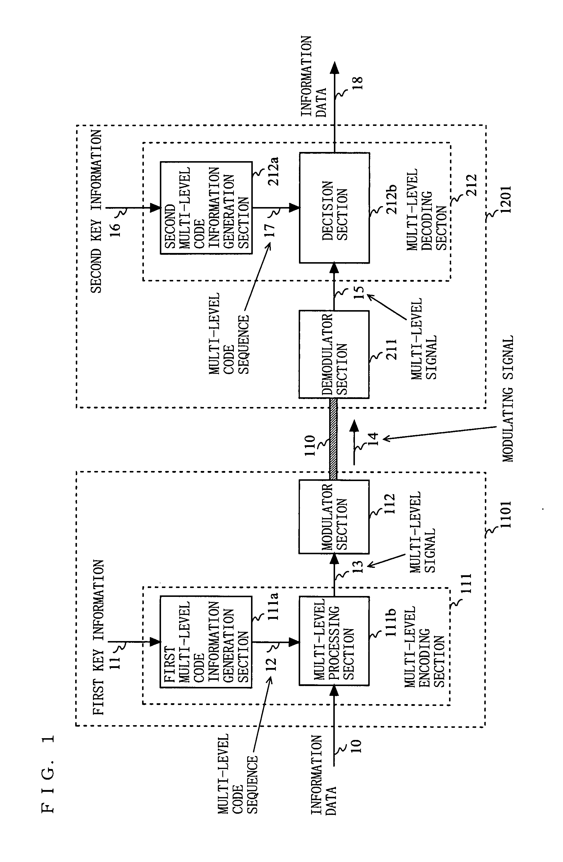
[0052]FIG. 1 is a block diagram showing an example of a configuration of a data communication apparatus according to the present invention. In FIG. 1, the data communication apparatus according to the first embodiment has a configuration in which a data transmitting apparatus 1101 and a data receiving apparatus 1201 are connected to each other via a transmission line 110. The data transmitting apparatus 1101 includes a multi-level encoding section 111 and a modulator section 112. The multi-level encoding section 111 includes a first multi-level code generation section 111a and a multi-level processing section 111b. The data receiving apparatus 1201 includes a demodulator section 211 and a multi-level decoding section 212. The multi-level decoding section 212 includes a second multi-level code generation section 212a and a decision section 212b. A metal line such as a LAN cable or a coaxial line, or an optical waveguide such as an optical-fiber cable can be used as the transmission l...

second embodiment

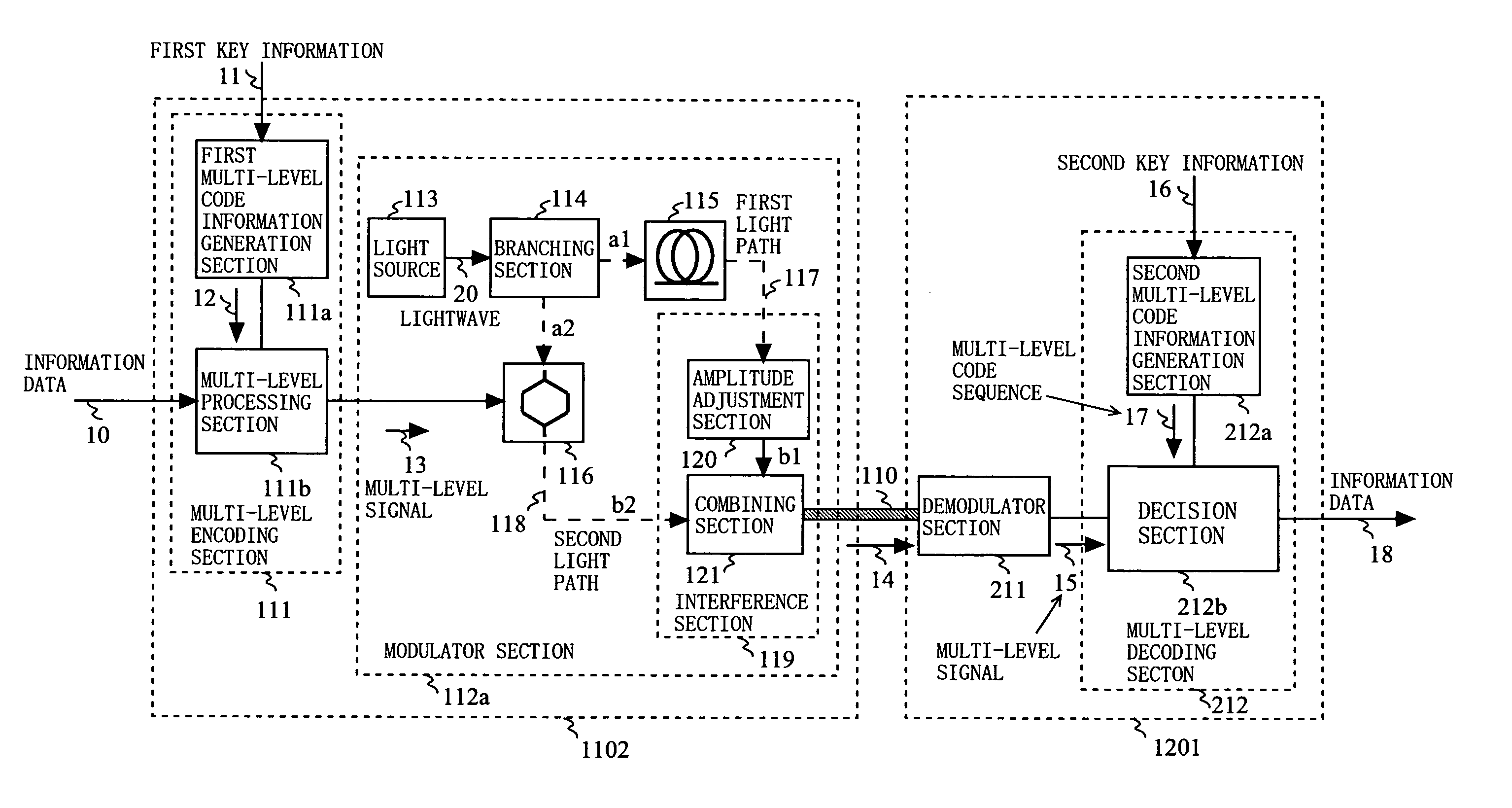
[0068]FIG. 6 is a block diagram showing an example of a configuration of a data communication apparatus according to a second embodiment of the present invention. In FIG. 6, the data communication apparatus according to the second embodiment of the present invention has a configuration in which a data transmitting apparatus 1102 and a data receiving apparatus 1201 are connected to each other via a transmission line 110. The data transmitting apparatus 1102 includes a first multi-level code generation section 111a, a multi-level processing section 111b, and a modulator section 112a. The data receiving apparatus 1201 includes a demodulator section 211, a second multi-level code generation section 212a, and a decision section 212b.

[0069] As shown in FIG. 6, the configuration of the data communication apparatus according to the second embodiment is different, with regard to a configuration of the modulator section 112a, from the data communication apparatus according to the above-descr...

third embodiment

[0082]FIG. 10 is a block diagram showing an example of a configuration of a data transmitting apparatus 1103 according to a third embodiment of the present invention. As shown in FIG. 10, the data transmitting apparatus 1103 according to the third embodiment is different, with regard to a configuration of a modulator section 112b, from the data transmitting apparatus 1101 according to the above-described first embodiment. Hereinafter, component parts of the configuration which are the same as the first embodiment are provided with common reference characters, and the data communication apparatus according to the third embodiment will be described by mainly focusing such component parts that are different from the first embodiment.

[0083] In FIG. 10, the modulator section 112b includes a light source 113, a branching section 114, an delaying section 115, a light modulator section 116, and an interference section 119. The interference section 119 has an amplitude adjustment section 12...


PUM


Abstract

A data communication apparatus which causes the eavesdropper to take a significantly increased time to analyze a cipher text and provides high concealability is provided. In a modulator section 112a, a branching section 114 branches a lightwave 20 outputted from a light source 113, and outputs respective branched lights to a first light path 117 and a second light path 118 respectively having different light path lengths. A light modulator section 116 modulates, based on a multi-level signal 13, a lightwave propagating at least one light path of the first light path 117 and the second light path 118. An interference section 119 causes the lightwaves outputted from the first light path 117 and the second light path 118 to interfere with each other, and outputs such interfered lightwave as a modulated signal 14.

Description

BACKGROUND OF THE INVENTION [0001] 1. Field of the Invention [0002] The preset invention relates to an apparatus and a method for performing secret communication in order to avoid illegal eavesdropping and interception by a third party, more particularly, relates to a data transmitting apparatus and a data transmitting method for performing data communication through selecting and setting a specific encoding / decoding (modulating / demodulating) method between a legitimate transmitter and a legitimate receiver. [0003] 2. Description of the Background Art [0004] Conventionally, in order to perform secret communication between specific parties, there has been adopted a structure for realizing secret communication by sharing key information for encoding / decoding between transmitting and receiving ends and by performing, based on the key information, an operation / inverse operation on information data (plain text) to be transmitted, in a mathematical manner. FIG. 17 is a block diagram showi...

Claims


Application Information

Patent Timeline
IPC IPC(8): H04L9/00
CPCH04B10/505H04B10/5055H04L25/4917H04B10/85H04K1/02H04B10/516
Inventor FURUSAWA, SATOSHIFUSE, MASARUIKUSHIMA, TSUYOSHISADA, TOMOKAZU
Owner PANASONIC CORP
Why Eureka
Try Eureka