Joint connector

a technology of joint connectors and connectors, which is applied in the direction of vehicle connectors, coupling device connections, electrical apparatus, etc., can solve the problems of reducing the efficiency of electric wire connecting operation by the joint connector, increasing the size of the joint connector itself, and the size of the terminal itself becomes large to a certain extent, so as to detect the upside-down insertion of the connecting terminal into the terminal-accommodating compartment quickly

Active Publication Date: 2007-08-30
FURUKAWA ELECTRIC CO LTD
View PDF12 Cites 20 Cited by
  • Summary
  • Abstract
  • Description
  • Claims
  • Application Information

AI Technical Summary

Benefits of technology

[0097] With this configuration, the electric wire is not lifted in an upward direction even when a tensile force acts on the electric wire in an upward direction after the connecting terminal are inserted and accommodated in the terminal-accommodating compartment, and the rear side of the lance and the connecting terminal in the connector housing can be prevented from breakage. Furtherm

Problems solved by technology

For this reason, in the use of the joint connector 100, cumbersome manufacturing steps such as bending-back of the terminals and cutting-off of the linking portion are required, which reduce efficiency in electric wire connecting operation by the joint connector.
Also, the third prior-art joint connector 300, which was described last, has a drawback in that it is provided with a press-fit blade for the stacking direction and a press-fit blade for the juxtaposed direction within one terminal and therefore the size of the terminal itself becomes large to a certain extent, accordingly increasing the size of the joint connector itself.
Moreover, after the terminals 310 are inserted and the one-stage parallel-line-shaped connectors 300 are stacked, electric wires need to be wired and fixed into a desired circuit, which reduces efficiency in the connection operation for the joint connector 300.
Apart from these problems, the first prior-art joint connector 100 and the second prior-art joint connector 200 in particular have a drawback in that, because they have a structure in which one terminal has both a female terminal portion and a male terminal portion, the terminal itself has a complex configuration, which requires a complex molding in manufacturing the terminal, and quality control for the terminals becomes difficult.
Furthermore, since both of the male terminal portion and the female terminal portion are manufactured from one sheet of metal plate, the electrical resistance is high in the male-female contacts or the like and accordingly heat generation becomes great due to the requirement for types of material and thickness that matches the spring characteristics of the female terminal portion (for example, brass having a thickness of 0.25 mm) Therefore, a limitation in use arises in that a sufficiently large current cannot pass.
However, in the work of fitting and connecting the connector, the inserting-side connector portion is often inserted into the receiving-side connector portion in an inclined state, and it is difficult to insert the inserting-side connector portion in a proper posture.
Since the inserting-side connector portion has a rigid structure, its insertion accordingly requires a great force.
In addition to this, there is a risk of causing poor electrical connection in the connector because the insertion might become impossible halfway or the connector housings or the connecting terminals might be deformed by an excessive force applied thereto.
Moreover, in many cases, the thickness of each of the connector housings does not become a uniform dimension since there is a dimensional tolerance.
In particular, in case of the minimum value within the dimensional tolerance, pitch between the connecting terminals when the connector housings which are stacked sometimes becomes smaller than a predetermined pitch, and thus does not match the pitch of the connection pins of the circuit-forming unit in the mating receiving-side connector portion.
Thus, there is also a risk of causing poor electrical connection in the connector s

Method used


Image

  • Joint connector
  • Joint connector
  • Joint connector

Examples


first embodiment

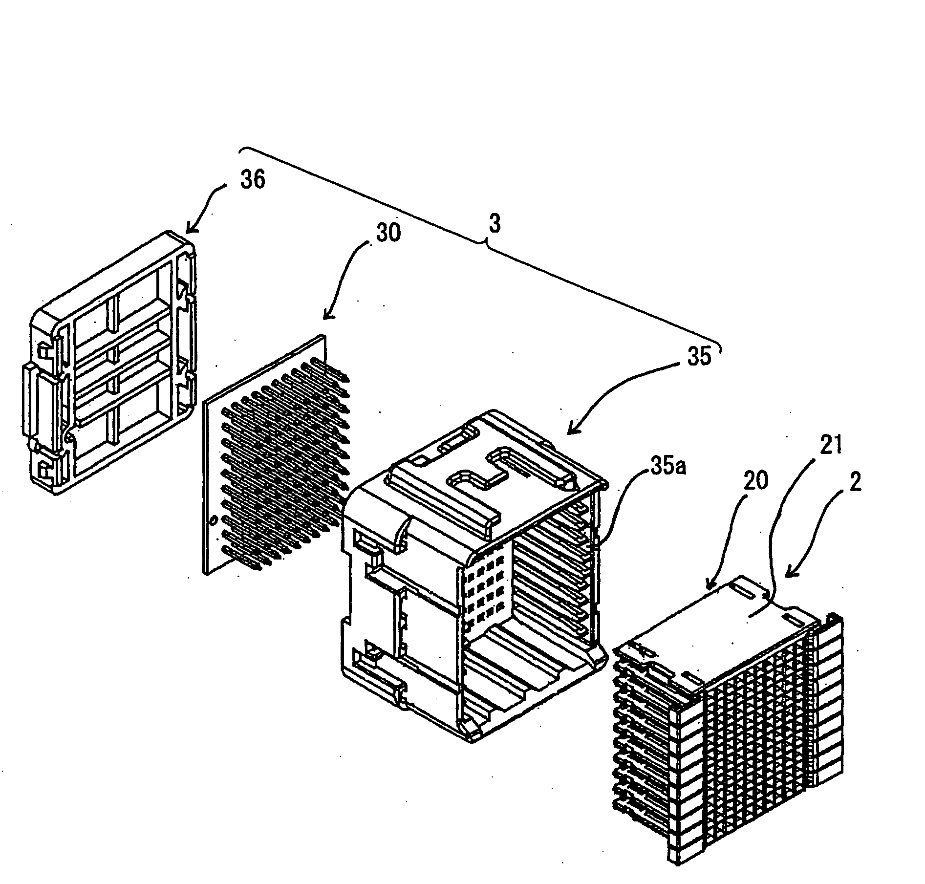
[0153] As shown in the exploded perspective view of FIG. 8 and the assembled view of FIG. 9, a joint connector 1 according to the present invention is provided with a female connector 2 having a large number of female terminals F, and a housing 35 in which the female connector 2 can be accommodated. It is also provided with a large number of male terminals M (see FIG. 11) for connecting the female terminals F (see FIG. 10) of the female connector 2, and a male connector 3 having a cover 36 attached on a side opposite to the side of the housing 35 into which the female connector is inserted.

[0154] As shown FIG. 10, the female connector 2 has a structure in which female connector elements 20, comprising a rectangular thick-plate-like female terminal holder (one-stage parallel-line-shaped connector housing) 21 and female terminals F juxtaposed in the female terminal holder 21, are stacked in a vertical direction. The female connector elements 20 correspond to each one of sub-harnesses,...

second embodiment

[0182] Now, a joint connector according to the present invention is described in detail with reference to the drawings.

[0183]FIG. 14 is an exploded perspective view showing a joint connector according to the second embodiment of the present invention, adapted to a multi-pin connector for automobile wire harnesses. FIG. 15 is an enlarged perspective view showing the joint connector in an assembled condition, in which the component parts of FIG. 14 are combined. FIG. 16 shows a connector housing constituting an inserting-side connector portion of FIG. 14, in which FIG. 16A is a perspective view thereof, viewed from its obverse side and FIG. 16B is a perspective view thereof, viewed from its reverse side. FIG. 17 shows a connector housing of FIG. 16, in which FIG. 17A is a top plan view thereof, and FIG. 17B is a bottom plan view thereof.

[0184] A joint connector according to the second embodiment of the present invention comprises, as shown in the above-mentioned figures, an inserting...

third embodiment

[0234] The joint connector according to the present invention is assembles as follows. In the terminal-accommodating compartments 619 of the connector housings 617, the female terminals connected to the terminals of the electric wires constituting a wire harness are accommodated, and the connector housings 617 are stacked, and are combined by the connector-coupling means 625, to obtain the inserting-side connector portion 611. Next, this inserting-side connector portion 611 is opposed to the receiving-side connector portion 613, the centers (axes) of both connector portions 611 and 613 are aligned, and the inserting-side connector portion 611 is inserted into the first accommodating space 633 of the connector case 621 in the receiving-side connector portion 613. Then, the claws 647 of the engaging claw portions 645 of the connector-locking means 615 are engaged with the engagement recess portions 643 to lock both connector portions 611 and 613, and the male terminals 623 of the rece...


PUM


Abstract

A joint connector according to the present invention is provided with a circuit board, a male connector having male terminals provided on the circuit board at a predetermined interval and standing in one direction and a direction that crosses the one direction, the male terminals being selectively connected by a copper foil circuit, and a female connector in which female connector elements each having female terminals inserted and interlocked in female terminal holders are stacked, wherein the male connector and the female connector are fit to each other. This achieves cost reduction and improvement in work efficiency in electric wire connection by attaining easy electric wire connection and branching.

Description

BACKGROUND OF THE INVENTION [0001] 1. Field of the Invention [0002] The present invention relates to joint connectors used for, for example, branching a wire harness (electric wires) wired in an automobile, and particularly to a joint connector that can achieve cost reduction and exhibit excellent workability in connecting electric wires. [0003] 2. Description of the Prior Art [0004] Hereinbelow, a first prior art and its problems to be solved are discussed. [0005] In recent years, electrical components incorporated in, for example, automobiles have increasingly been diversified. This has created the necessity of branching wire harnesses in complex manners, and accordingly, there has been a greater use of joint connectors. [0006] Here, an example of prior-art joint connectors is described. One example of the terminal in a first prior-art joint connector of this kind has a male terminal portion and a female terminal portion provided in one piece of terminal and an electric wire press...

Claims


Application Information

Patent Timeline
IPC IPC(8): H01R13/514
CPCH01R4/185H01R13/514H01R2201/26H01R31/08H01R13/6658
Inventor MURAKAMI, MASAKAZUIMAI, TAKAHIROTAKABAYASHI, TAMAKIYABU, TAKENOBUTOMITA, SYOUGOUENO, SEIICHITAKEDA, KATSUNORI
Owner FURUKAWA ELECTRIC CO LTD
Why Eureka
Try Eureka