
Memory structure for optimized image processing

a memory structure and image processing technology, applied in the field of memory structures, can solve the problems of inefficient and slow operation, less than optimal performance, and limited memory access mechanism effect,

Inactive Publication Date: 2007-08-30
STMICROELECTRONICS INT NV
View PDF3 Cites 0 Cited by
  • Summary
  • Abstract
  • Description
  • Claims
  • Application Information

AI Technical Summary

Benefits of technology

The present disclosure provides a memory architecture that is efficient for image rotation by 90 degrees or a multiple of 90 degrees. The architecture includes a memory array with multiple multi-byte memory data paths of equal width and a multiplexing structure that selectively provides a desired width containing a desired permutation of bytes from one or more of the data paths. This architecture is capable of rotating, separating, mirroring, and generating planar data from an image. The technical effect of this invention is to provide a more efficient and faster memory architecture for image processing.

Problems solved by technology

The resulting performance is less than optimal as the typical frequently used functions of image translation or rotation very often require non-sequential memory access.
Consequently, several memory accesses are required for each step of the image processing function resulting in inefficient and slow operation for a given clock speed.
Typically, such systems focus on determining the optimum movement of the data regardless of the speed of accessing data from the memory without addresses the issues relating to the speed and efficiency of accessing the data from the memory, hence its effectiveness is limited by the memory access mechanism.

Method used


Image

  • Memory structure for optimized image processing
  • Memory structure for optimized image processing
  • Memory structure for optimized image processing

Examples


Embodiment Construction

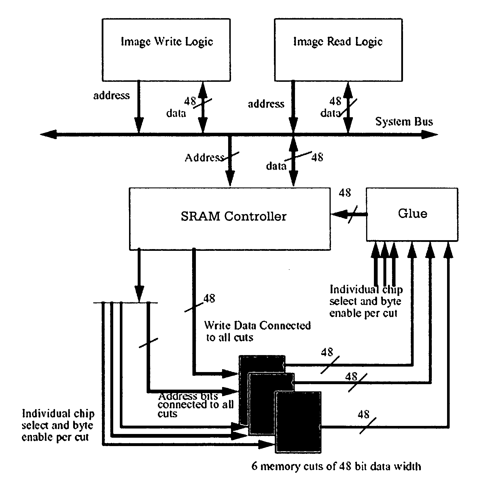
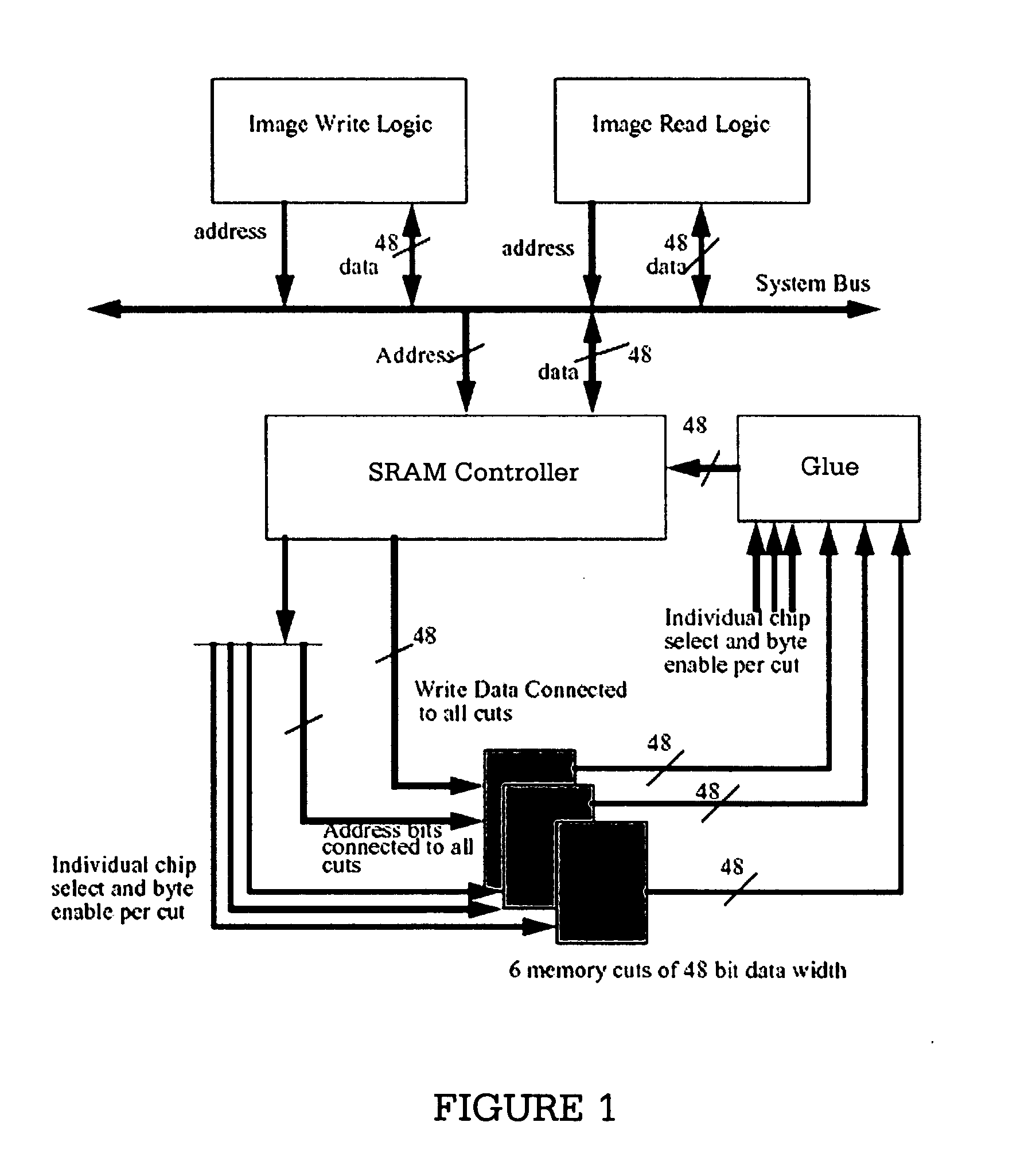
[0018] Embodiments of the present disclosure enable efficient utilization of the system bus bandwidth for image manipulation functions. A preferred embodiment of the disclosure, shown in FIG. 1, uses six memory cuts each of forty eight data width, along with simple read write control logic and a data multiplexer.

[0019] The embodiment shown in FIG. 1 is capable of the best bus performance for the 16-bits and 24-bits per pixel modes. This structure can be extended to support other formats with slight alteration. These signals are used in the data multiplexer to pack the data so that all the bits can be used. The data read and data write logic blocks are connected with the system bus for receiving data inputs and control signals.

[0020] In a preferred embodiment, the data width used is 48-bits wide. However, this is not a necessary restriction and the data width can be adjusted according to requirements. The memory system is preferably organized as six equal memory cuts of 48-bit wide...


PUM


Abstract

A memory architecture for image processing comprising a memory array having multiple multi-byte memory data paths of equal multi-byte data width, and a multiplexing structure connected to the output of the multiple multi-byte data paths, capable of selectively providing a multi-byte data path of a desired width containing a desired permutation of bytes chosen from one or more of the multiple data paths.

Description

CROSS-REFERENCE TO RELATED APPLICATIONS [0001] This patent application claims priority under 35 U.S.C. § 119(a) to Indian Patent Application No. 3549 / Del / 2005 entitled “MEMORY STRUCTURE FOR OPTIMIZED IMAGE PROCESSING” filed on Dec. 30, 2005, which is hereby incorporated by reference. Indian Patent Application No. 3549 / Del / 2005 is assigned to the assignee of the present application and is hereby incorporated by reference into the present disclosure as if fully set forth herein. The present application hereby claims priority under 35 U.S.C. §119(a) to Indian Patent Application No. 3549 / Del / 2005. TECHNICAL FIELD [0002] The present disclosure relates to memory structures and in particular to memory structures for image rotation and mirroring. BACKGROUND [0003] Image processing is an essential function of a vast majority of modern day devices, ranging from computing systems to consumer devices such as cell phones and Personal Digital Assistants (PDAs). The human interfaces for these devi...

Claims


Application Information

Patent Timeline
Patent Type & Authority Applications(United States)
IPC IPC(8): G06F12/06
CPCG06T1/60
Inventor CHANDRA, MAHESH
Owner STMICROELECTRONICS INT NV
Learn More