

Reforming apparatus, internal combustion engine with reforming apparatus, and fuel cell system with reforming apparatus
a technology of internal combustion engine and reforming apparatus, which is applied in the direction of mechanical equipment, machines/engines, and non-fuel substance addition to fuel, etc., can solve the problems of difficult to use the fuel obtained by the related method as a fuel for an internal combustion engine, significant increases in the cost and size of the separation system, etc., and achieves simple and compact effect, enhancing the fuel consumption rate of internal combustion engin
- Summary
- Abstract
- Description
- Claims
- Application Information
AI Technical Summary
Benefits of technology
Problems solved by technology
Method used
Image


Examples
first embodiment
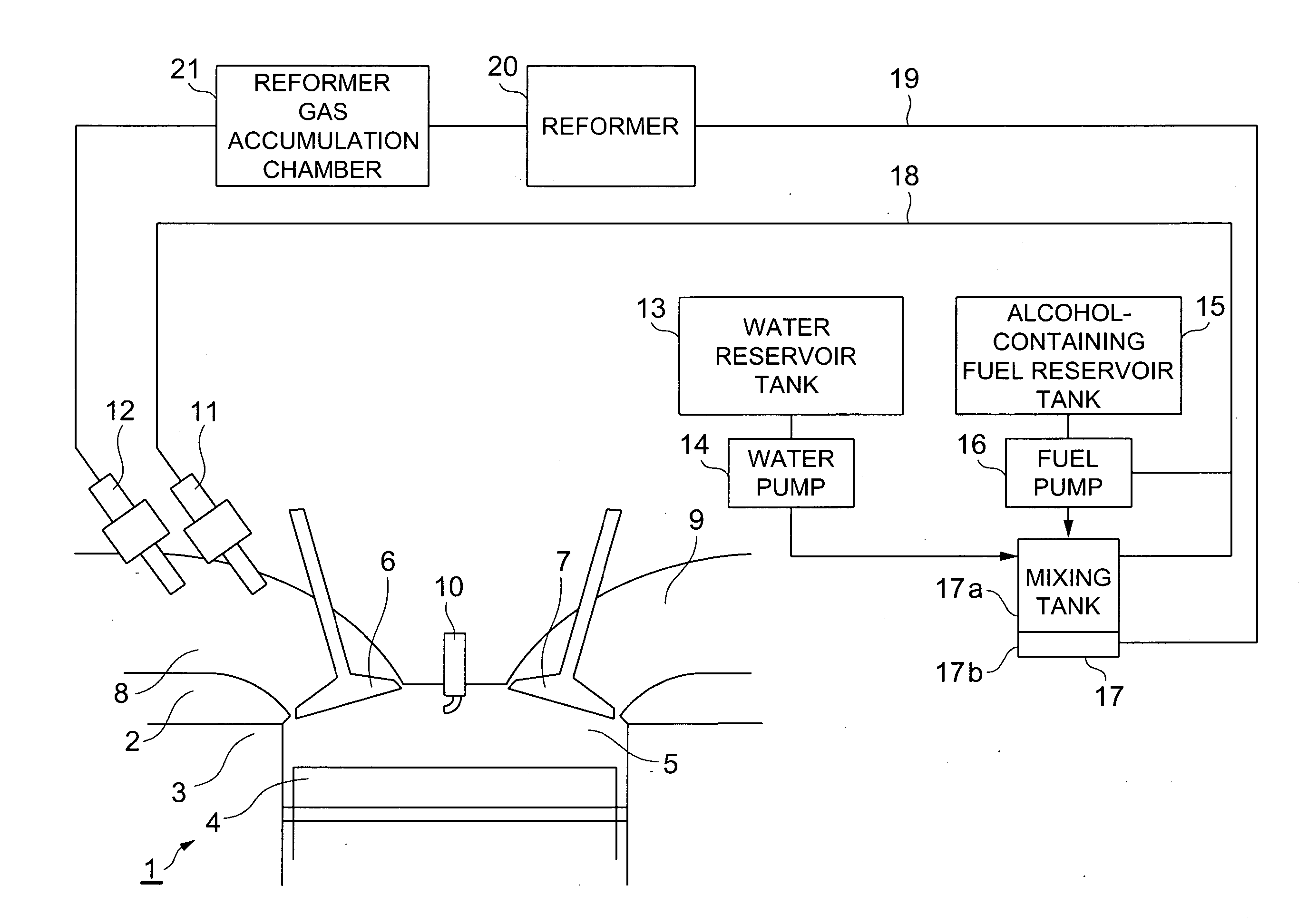
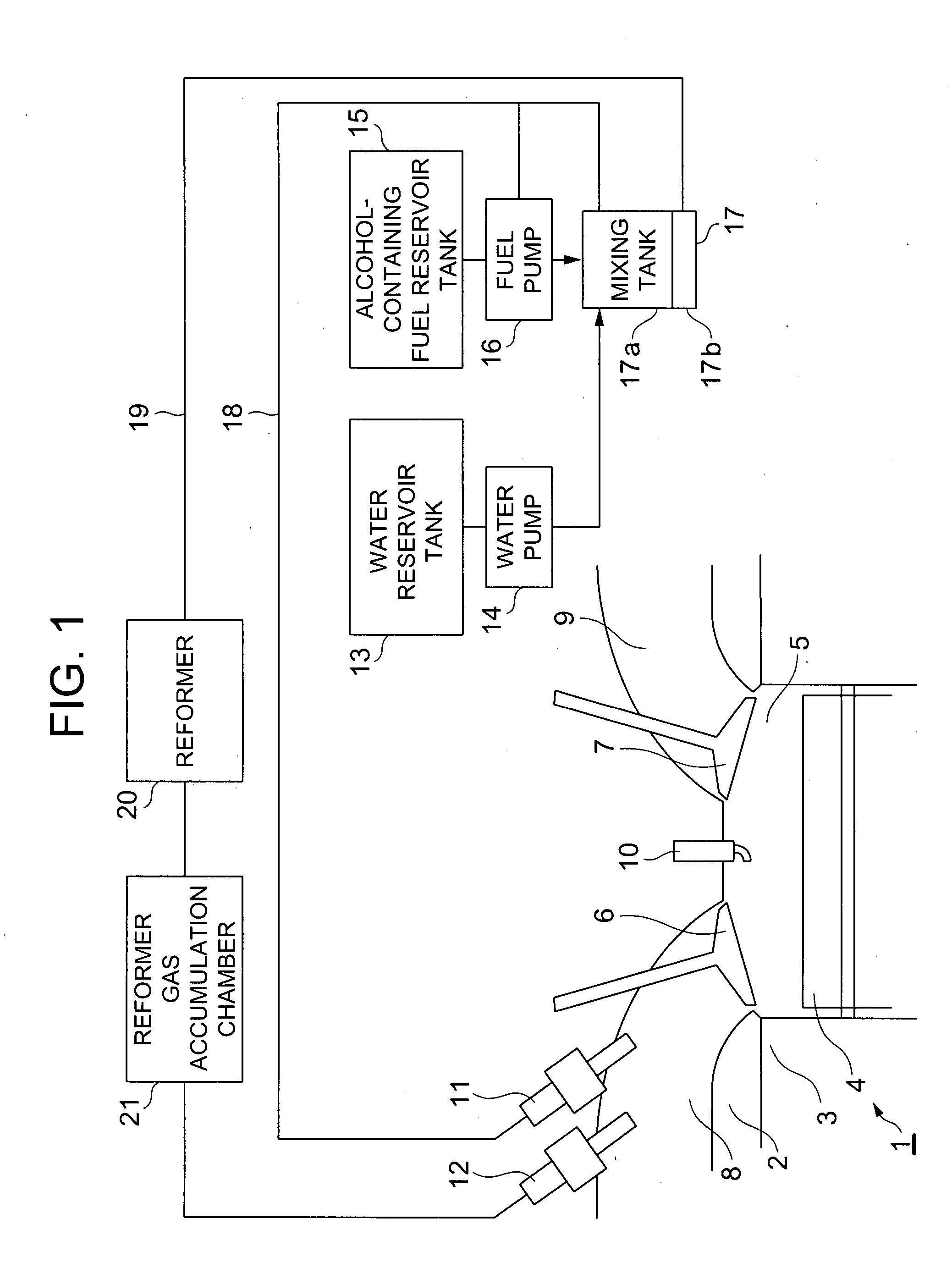
[0017] Referring to a first embodiment shown in FIG. 1, a heat engine system may include an internal combustion engine 1, which preferably includes a cylinder head 2, a cylinder block 3, and a piston 4, which together define a combustion chamber 5. An intake valve 6 and an exhaust valve 7 separate an intake port 8 and an exhaust port 9, respectively, from combustion chamber 5. The intake valve 6 opens to allow ingress of fresh combustion components into the combustion chamber 5, and the exhaust valve 7 opens to allow egress of spent combustion products from the combustion chamber 5. Closing the intake and exhaust valves 6, 7 allows compression of the combustion components and allows expansion of the combustion products.
[0018] A spark or ignition plug 10 is preferably disposed substantially near the center of an upper section of combustion chamber 5. A main fuel injection valve 11 and a reformed gas injection valve 12 are disposed in intake port 8, and will be further described herei...
third embodiment
[0041] In accordance with a further aspect of the third embodiment, main portion 5A of combustion chamber 5 has a larger volumetric capacity than auxiliary chamber 27, and reformed gas tube 19A and check valve 29 provide an induction means for inducting the reformed gas into auxiliary chamber 27 of combustion chamber 5. Accordingly, it is possible to significantly improve fuel efficiency by inducting hydrogen, or a gas containing hydrogen, into auxiliary chamber 27 and thereby expand the limit for operating the main chamber 5A in a lean state. Further, on a heating value basis, it is sufficient to provide an extremely small quantity of fuel in auxiliary chamber 27 with respect to the quantity of fuel supplied to main chamber 5A. Therefore, fuel containing an extremely low alcohol content, e.g., approximately 10% alcohol, is sufficient to be effective. Since the quantity of fuel to be reformed is small, the required quantity of water is also small and reservoir tank 13 may be compact...
second embodiment
[0045] In accordance with a further aspect of the second embodiment, the condenser 23 may provide condensed (i.e., liquefied) water by cooling water vapor in the combustion products exhausted from combustion chamber 5. The condensed water may then be supplied to reservoir tank 13 (e.g., via condensed water pump 25, and condensed water tube 26). Preferably, a majority of the water required in the fuel reforming apparatus may be provided by the condensed water, thereby minimizing the need to supply additional water to reservoir tank 13. Moreover, a more compact reservoir tank 13 may be provided. Since condenser 23 preferably includes a cooling section in a part of the exhaust pipe, it is relatively easy and efficient to cool the exhaust gas in the cooling section and obtain the liquefied condensed water in a recovery section that is also easily arranged in a part of the exhaust pipe.
[0046] In accordance with a further aspect of the second embodiment, a filter may provide a means for p...
PUM
 Abstract
Description
Claims
Application Information