Composite pressure tank and process for its manufacture

a technology of composite pressure tanks and pressure vessels, applied in the field of pressure vessels, can solve the problems of high thermal stress at the interface, rupture of the vessel, and thermal stress problem of composite pressure vessels with metallic liners, and achieve the effect of low cost and low weigh

Inactive Publication Date: 2007-09-06
MICROCOSM INC
View PDF5 Cites 68 Cited by
  • Summary
  • Abstract
  • Description
  • Claims
  • Application Information

AI Technical Summary

Benefits of technology

[0020] It will be appreciated from the foregoing summary that the present invention represents a significant advance in the field of pressure vessel fabrication for cryogenic, space and other applications. In particular, a vessel formed by overwrapping a composite liner shell with additional composite material has relatively low weight and low cost. Other aspects and advantages of the invention will become apparent from the following more detailed description, taken in conjunction with the accompanying drawings.

Problems solved by technology

Unfortunately, composite pressure vessels with metallic liners present a thermal stress problem, when used to store cryogenic materials.
Specifically, significant differences in the coefficients of thermal expansion (CTE), between the metallic liner and the composite outer shell, result in high thermal stresses at the interface.
These thermal stresses can be significant enough to cause rupture of the vessel if not addressed.
A vessel fabricated with only composite materials would obviate the disadvantages of using a metallic liner.
Composite pressure vessels for aerospace applications can be very expensive due largely to the need for an autoclave.
Autoclaves control the temperature and pressure during curing and can be expensive devices, especially if the vessels to be manufactured are large.

Method used


Image

  • Composite pressure tank and process for its manufacture
  • Composite pressure tank and process for its manufacture
  • Composite pressure tank and process for its manufacture

Examples


Embodiment Construction

[0059] In the following description, reference is made to the accompanying drawings which form a part hereof, and which is shown, by way of illustration, several embodiments of the present invention. It is understood that other embodiments may be utilized and structural changes may be made without departing from the scope of the present invention.

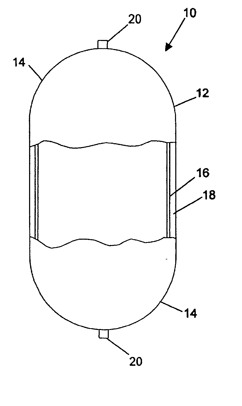
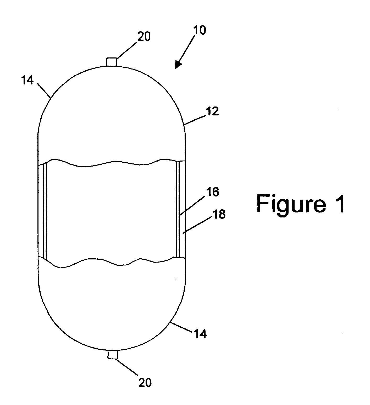
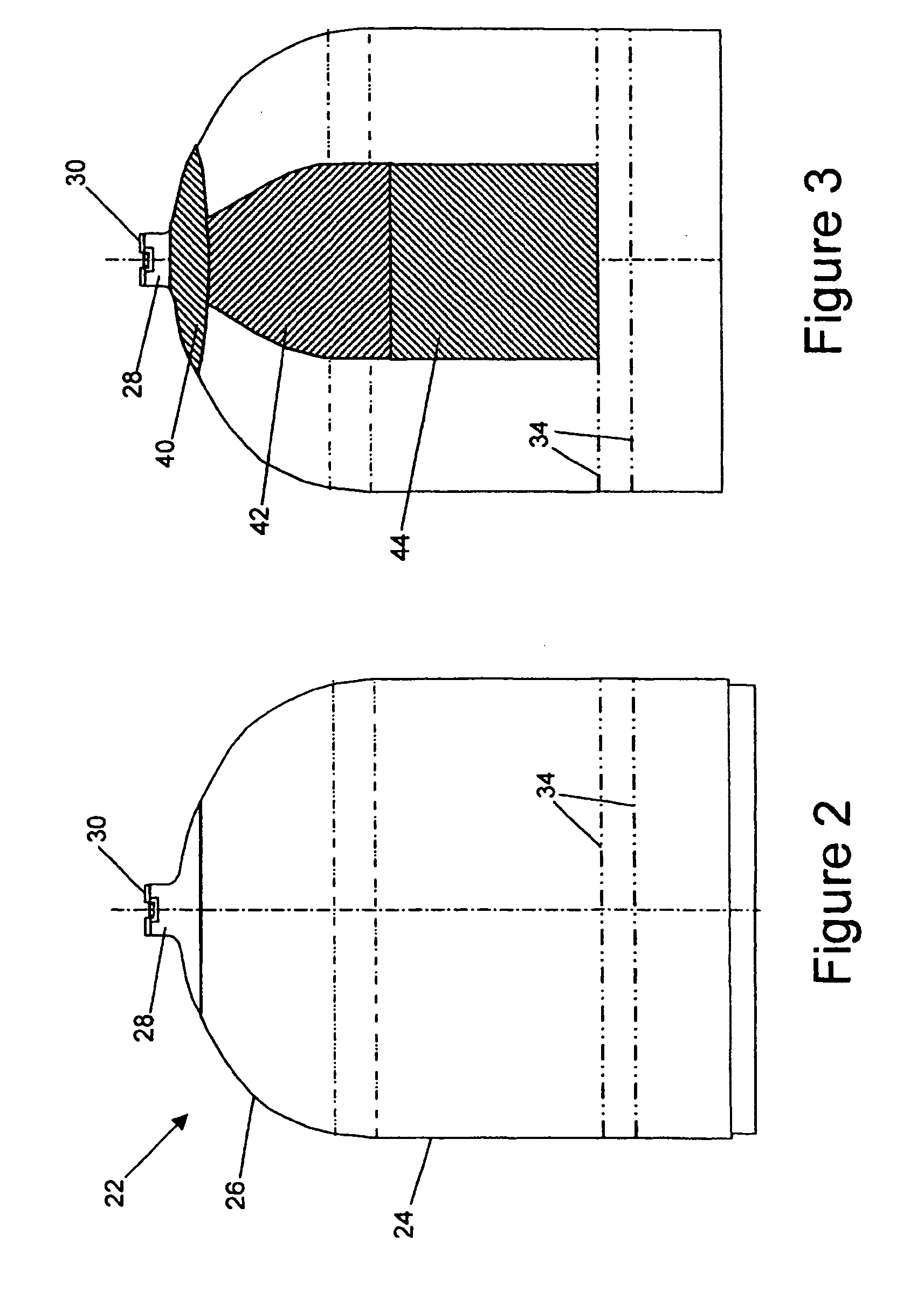
[0060] As shown in the drawings for purposes of illustration, the present invention pertains to pressure vessels for use in applications in which weight, cost, or both are important concerns. Although the invention was made with launch vehicle propellant tanks and other space vehicle applications in mind, it may also be usefully applied in other fields. In the past, pressure vessels of this general type have been made to include a metal liner, or have been made in part from composite materials that must be cured the controlled temperature and pressure environment of an autoclave.

[0061] In accordance with the present invention, a pressure ...


PUM

PropertyMeasurementUnit
angleaaaaaaaaaa
angleaaaaaaaaaa
fiber angleaaaaaaaaaa

Abstract

A pressure vessel and method for producing a pressure vessel is disclosed. The pressure vessel comprises a liner shell fabricated from composite material applied to a soluble mandrel having a body shaped to pattern an interior of the pressure vessel, the liner shell having an opening, a boss having an aperture therethrough, the boss sealingly bonded to the liner shell with the aperture adjacent the opening, and an outer shell fabricated from plies of composite material filament impregnated with matrix material wound over the liner shell and the boss, but not over the aperture.

Description

CROSS-REFERENCE TO RELATED APPLICATIONS [0001] This application is a continuation-in-part of co-pending and commonly assigned application Ser. No. 10 / 121,737, entitled “COMPOSITE PRESSURE TANK AND PROCESS FOR ITS MANUFACTURE,” by Roy S. Cundiff and Anthony Mancuso, filed Apr. 12, 2002, which application is hereby incorporated by reference herein.BACKGROUND OF THE INVENTION [0002] 1. Field of the Invention [0003] The present invention relates generally to pressure vessels, and more particularly, to pressure vessels used for storage of cryogenic and other materials in rocket launch and space vehicle applications. [0004] 2. Description of the Related Art [0005] In aerospace applications, pressurized propellant tanks may be fabricated by filament winding fiber reinforcement over a thin walled metallic liner. Carbon or fiberglass fibers provide the required strength without the weight penalty associated with an all-metallic tank. Unfortunately, composite pressure vessels with metallic li...

Claims


Application Information

Patent Timeline
Patent Type & Authority Applications(United States)
IPC IPC(8): F17C1/06
CPCF17C1/04F17C2270/0197F17C2201/054F17C2201/056F17C2203/0604F17C2203/0607F17C2203/0619F17C2203/0636F17C2203/0663F17C2203/0665F17C2203/067F17C2205/0323F17C2205/0397F17C2209/21F17C2209/2109F17C2209/2154F17C2209/227F17C2209/228F17C2209/23F17C2221/08F17C2223/0161F17C2223/033F17C2260/012F17C2260/035F17C2270/0186F17C2270/0194F17C2201/0109F17C1/06
Inventor CUNDIFF, ROY S.LEICHNER, AARON S.
Owner MICROCOSM INC
Why Eureka
Try Eureka