Plastic Optical Fiber And Method For Manufacturing The Same

Inactive Publication Date: 2007-09-06
FUJIFILM CORP
View PDF4 Cites 7 Cited by
  • Summary
  • Abstract
  • Description
  • Claims
  • Application Information

AI Technical Summary

Benefits of technology

[0008] In order to achieve the above objects, the inventors have found out that the polymer molecules in the POF are oriented when a heated POF is supplied with tension, especially just after the melt-drawing process in which heat and tension are applied to the polymer. While the rolled POF is in storage, the molecules in the POF are less oriented so that the POF gets shrunk in the lengthwise direction in which the orientation of the p

Problems solved by technology

Thereby, the POF is deformed during storage of POF,

Method used


Image

  • Plastic Optical Fiber And Method For Manufacturing The Same
  • Plastic Optical Fiber And Method For Manufacturing The Same
  • Plastic Optical Fiber And Method For Manufacturing The Same

Examples


first embodiment

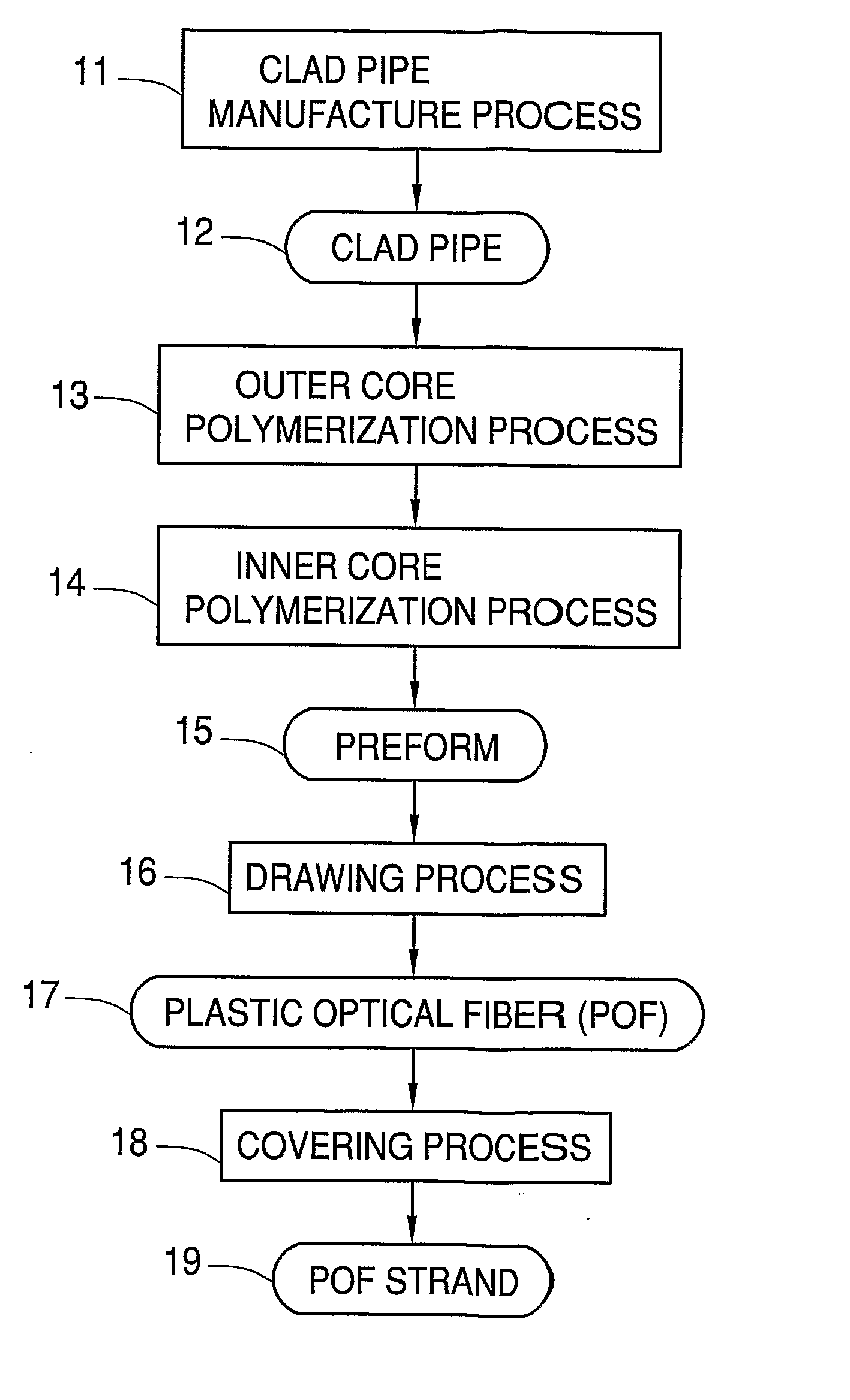
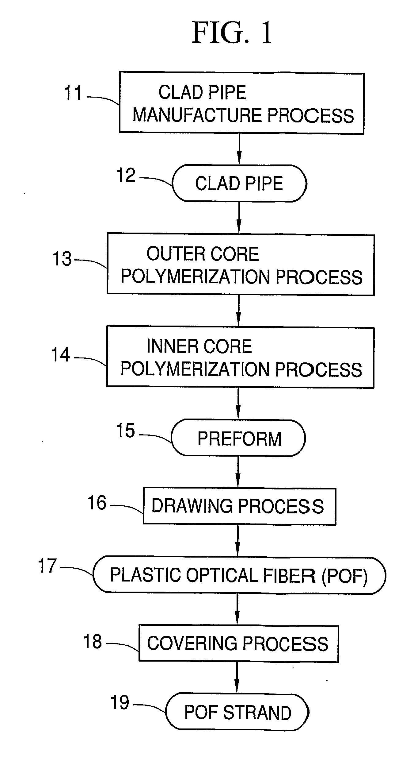
[0052] In the first embodiment, the polymerizable compositions for the clad part are polymerized to form a hollow pipe. Instead, the hollow cylindrical pipe is formed by melt extrusion of thermoplastic resin (1st process). The core part is formed by interfacial gel polymerization of the polymerizable composition for the core part in the hollow cylindrical pipe, so the preform having the core part and the clad part is produced (2nd process). The preform is subject to change its shape by the method and apparatus according to the present invention (3rd process) to manufacture the POF.

[0053] In the second embodiment, the outer core part is formed inside the hollow pipe corresponding to the clad part of the first embodiment (1'st process). In this embodiment, the core part located in the center of the preform is referred to as the inner core part. In the following description, the term “core part” also indicates the “inner core part”.

[0054] For instance, the hollow cylindrical pipe is f...

second embodiment

[0055] Although the double layered cylindrical pipe is formed step by step as described above, it is possible to form the double layered cylindrical pipe by a single step of melt extrusion of resin including fluorine for the clad part and the polymerizable composition for the outer core part.

[0056] The composition of the polymerizable monomers for the clad part is preferably the same as that for the core part according to the first embodiment. In the second embodiment, the composition of the polymerizable monomers for the outer core part is preferably the same as that for the inner core part. The composition ratio of the polymerizable monomers is not necessary the same, and an accessory ingredient to be added to the polymerizable monomers is not necessary the same. Providing the same kinds of the polymerizable monomers can improve the optical transmittance and the adhesiveness at the interface between the clad part and the core part (or at the interface between the outer core part ...


PUM

PropertyMeasurementUnit
Temperatureaaaaaaaaaa
Pressureaaaaaaaaaa
Pressureaaaaaaaaaa

Abstract

A preform (15) having a clad part of PVDF and a core part of PMMA is manufactured. The preform (15) is partially heated in a heating furnace (74) of 240° C. The preform (15) is subject to the melt-drawing process to form a plastic optical fiber (17). The drawing tension to the preform (15) is measured by use of a drawing tension measure device (76). Based on the measured value, a drawing roller pair (78) adjusts the drawing tension to be 3.8 MPa. The plastic optical fiber (17) is fed via a dancer roller (82) and rollers (84, 86) toward a bobbin (87) to wind the plastic optical fiber (17). A winding tension measure device (85) measures the winding tension to the POF (17). Based on the measured value, the dancer roller (82) changes its position to adjust the winding tension to be 2.5 MPa.

Description

TECHNICAL FIELD [0001] The present invention relates to a plastic optical fiber and a method for manufacturing the plastic optical fiber. BACKGROUND ART [0002] Recent development in communication industry, the demand for the optical fiber with lower transmission loss and low manufacture cost has been increased. A plastic optical part has merits of design facility and low manufacture cost, compared with a glass optical part with identical structure, so the plastic optical part has been recently utilized as an optical fiber, an optical lens element, an optical waveguide and so forth. Especially, a plastic optical fiber (referred to as “POF”), entirely composed of a plastic is suitable for manufacture of the optical fiber with large diameter at a low cost, because the POF has advantages in excellent flexibility, light weight and high machinability, compared with the glass optical fiber. Accordingly, it is planned to utilize the plastic optical fiber as an optical transmission medium fo...

Claims


Application Information

Patent Timeline
IPC IPC(8): B29D11/00G02B6/02G02B6/00
CPCG02B6/02038B29D11/00721G02B6/00
Inventor SATO, TAKANORIKARAKI, HIDEYUKIKEGASAWA, TADAHIRO
Owner FUJIFILM CORP
Why Eureka
Try Eureka