Transponder for in-Wheel Motor System and Wheel Therewith

a technology of in-wheel motor and transponder, which is applied in the field of transponders, can solve the problems of difficult battery replacement, high time and trouble, and achieve the effect of efficient supply of electric energy to the sensor section and excellent

Inactive Publication Date: 2007-09-06
YOKOHAMA RUBBER CO LTD
View PDF1 Cites 6 Cited by
  • Summary
  • Abstract
  • Description
  • Claims
  • Application Information

AI Technical Summary

Benefits of technology

[0042] According to a transponder and a wheel therewith of the present invention, an electric current is supplied to a coil to form a magnetic field and to change flux density penetrating through another coil, and induced electric power generated at another coil is rectified, thus supplying electric energy to a sensor section more efficiently than a case where an electromagnetic wave is used as medium.
[0043] Since the electric current obtained by rectifying induced electric power generated at another coil is significantly larger than electric current required by a transponder, a storage device is constituted of a large-capacity capacitor or a secondary battery for sufficient storage, thus yielding very excellent effects that a main circuit as well as the sensor section can be driven and a transponder can be semipermanently operated by a storage device without need for a power supply.
[0044] The foregoing and / or further objects, features and advantages of the invention will become more apparent from the following description of preferred embodiments with reference to the accompanying drawings.
[0045]FIG. 1 is a cross-sectional view illustrating an outlined structure of a wheel used for an in-wheel motor system according to the first embodiment of the present invention;
[0046]FIG. 2 is a cross-sectional view taken on line A-A of FIG. 1;
[0047]FIG. 3 is a view illustrating communication between a transponder and a monitor unit according to the first embodiment of the present invention;

Problems solved by technology

However, most of conventional transponders use a battery to operate an internal electronic circuit respectively and, if the battery becomes exhausted, will not operate.
Therefore, periodical replacement of the battery is required, which requires much time and trouble.
In a structure having the transponder therein, battery replacement is not easy to perform.

Method used


Image

  • Transponder for in-Wheel Motor System and Wheel Therewith
  • Transponder for in-Wheel Motor System and Wheel Therewith
  • Transponder for in-Wheel Motor System and Wheel Therewith

Examples


Embodiment Construction

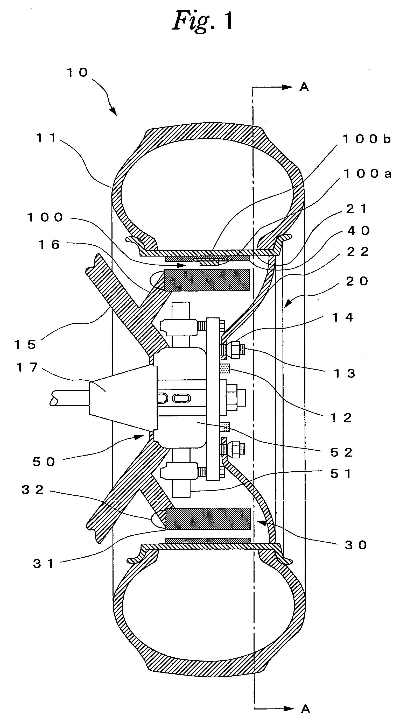
[0054] Reference will be made in detail to preferred embodiments of the invention, examples of which are illustrated in the accompanying drawings.

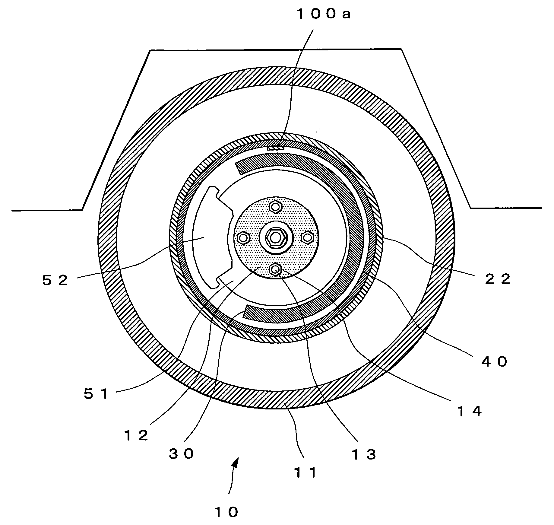
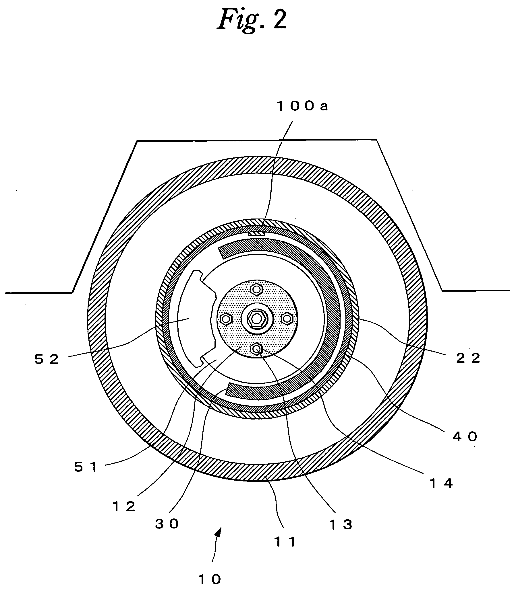
[0055]FIG. 1 is a cross-sectional view illustrating an outlined structure of a wheel used for an in-wheel motor system according to the first embodiment of the present invention, and FIG. 2 is a cross-sectional view taken on line A-A of FIG. 1.

[0056] In figures, a wheel 10 is a wheel for an in-wheel motor system with an induction motor built therein and includes a tire 11 and a wheel 20 mounted with a tire 11. The wheel 20 has a rim section 21 for mounting the tire 11, and a disc section 22 for coupling the rim section 21 to a hub 12.

[0057] Usually four to six stud bolts 13 vertically set on the hub 12 are passed through holes formed in the disc section 22 and secures the whole wheel 20 with hexagonal nuts 14 respectively. The hub 12 is rotatably supported on a wheel supporting section 15 through bearings or the like and rotates togethe...


PUM


Abstract

A transponder which does not require a power source used in an in-wheel motor system and a wheel therewith. The transponder comprises a data transmit/receive antenna, a data transmit/receive section, a sensor circuit, and a sensor power circuit. The sensor power circuit is constituted of a rectification circuit (energy converting means), a storage device and a charging coil and the input side of the rectification circuit is connected to a charging coil and the output side of the rectification circuit is connected to the storage device. The transponder is mounted on a motor rotor provided on an internal surface of a rim section in a tire constituting the wheel, and the charging coil is fixed so as to penetrate through a magnetic field produced by a motor stator.

Description

TECHNICAL FIELD [0001] The present invention relates to a transponder which does not require a power source used in an in-wheel motor system and a wheel therewith. BACKGROUND ART [0002] To identify a tire or obtain information such as inner pressure, temperature and rotational speed of a tire, there is known a technique of such a type as to receive electric oscillating energy from a position distant from a specific tire and to transmit a signal from a transponder mounted on a wheel including the tire. [0003] The transponder consists of an integrated circuit and a case for protecting the integrated circuit and the shape thereof is small coin-shaped or columnar or the like. [0004] As this type of technique, there is conventionally proposed a transponder of which embedding position is set at the central portion of a front end level of carcass ply winding section or on a carcass ply outer surface of a pat-less section (for example, refer to Patent Literature 1). [0005] Furthermore, a pn...

Claims


Application Information

Patent Timeline
Patent Type & Authority Applications(United States)
IPC IPC(8): B60C23/00B60C23/04B60K7/00B60L3/00H04B1/59
CPCB60C23/0413B60C23/043B60C23/0438B60K7/0007Y02T10/641B60K2007/0092G01D21/00H02K7/1846B60K2007/0038B60L1/00B60L3/0038B60L2220/44Y02T10/64
Inventor HATTORI, YUTAKAHATANO, YASUO
Owner YOKOHAMA RUBBER CO LTD
Why Eureka
Try Eureka