
Hybrid vehicle system having engine with variable valve operation

a technology of variable valve operation and hybrid propulsion system, which is applied in the direction of machines/engines, non-mechanical valves, electrical control, etc., to achieve the effect of improving the operation of the hybrid propulsion system, improving engine shut-down and hot restart operation, and improving the utilization of hybrid propulsion system

Active Publication Date: 2007-09-13
FORD GLOBAL TECH LLC
View PDF11 Cites 51 Cited by
  • Summary
  • Abstract
  • Description
  • Claims
  • Application Information

AI Technical Summary

Benefits of technology

[0001] Engines have used various forms of variable cam timing to improve engine operation over a variety of speed / load conditions. Variable cam timing adjusts the relative timing of the camshaft to the crankshaft, thus changing valve opening / closing timing relative to piston movement.
[0005] In this way, by using default positions in which intake and exhaust valve timings are in retarded positions, it is possible to better utilize operation of the hybrid propulsion system. For example, improved engine shut-down and hot restart operation may be obtained to improve hybrid system operation. Further, it is possible to utilize the hybrid propulsion system to avoid engine operation where earlier timing may be desired, yet the actuator system is in it default position. For example, the hybrid system may be able to adjust engine speed to avoid or reduce conditions of insufficient hydraulic pressure. As another example, if earlier timing is desired during warmed-up idle conditions where desired speed is low (and thus pressure may be low), the engine may be shut-off.

Problems solved by technology

However, the inventors herein have recognized several issues with such approaches.
For example, there may be conflicting requirements in selecting the default (locking pin) position.

Method used


Image

  • Hybrid vehicle system having engine with variable valve operation
  • Hybrid vehicle system having engine with variable valve operation
  • Hybrid vehicle system having engine with variable valve operation

Examples


Embodiment Construction

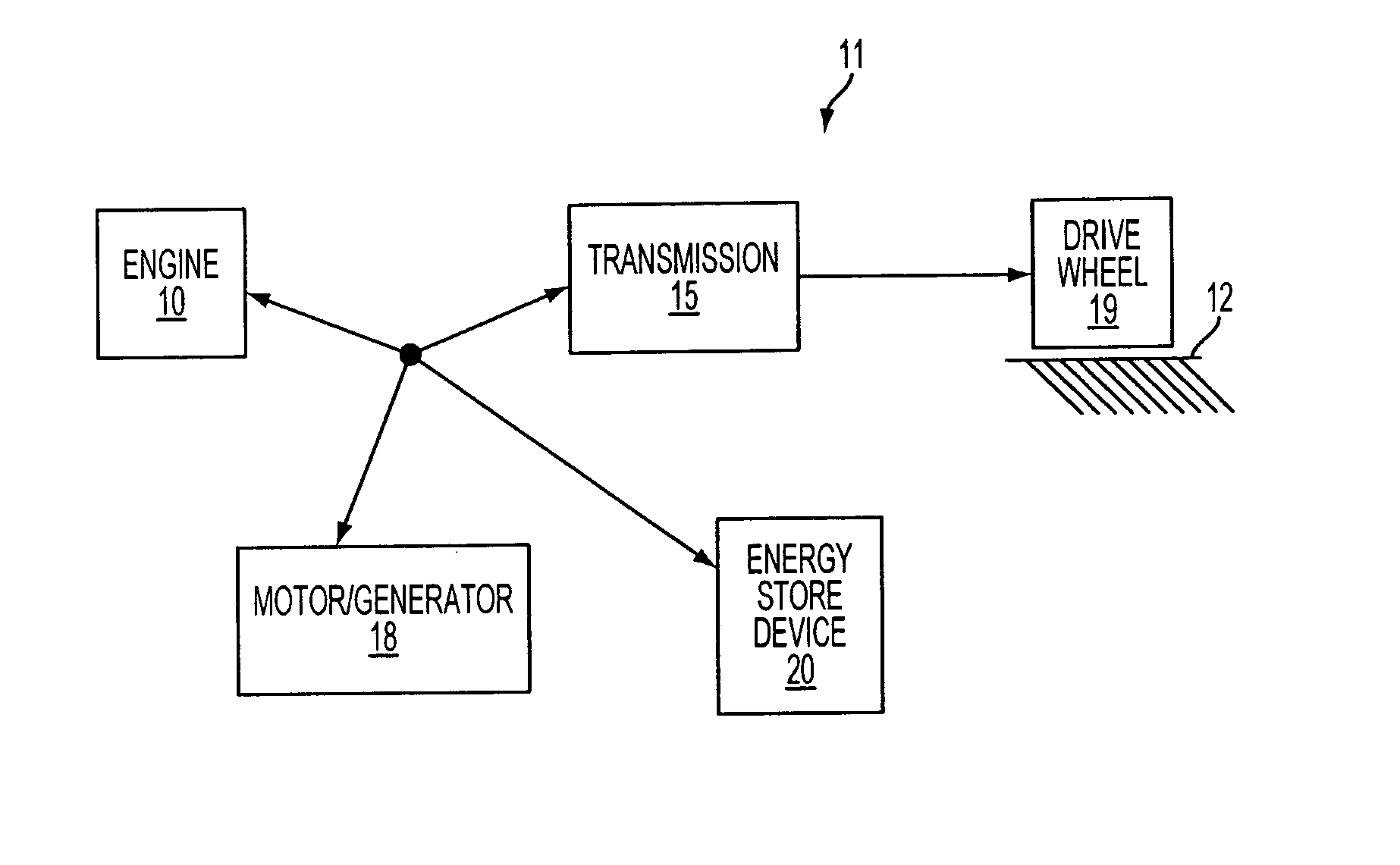
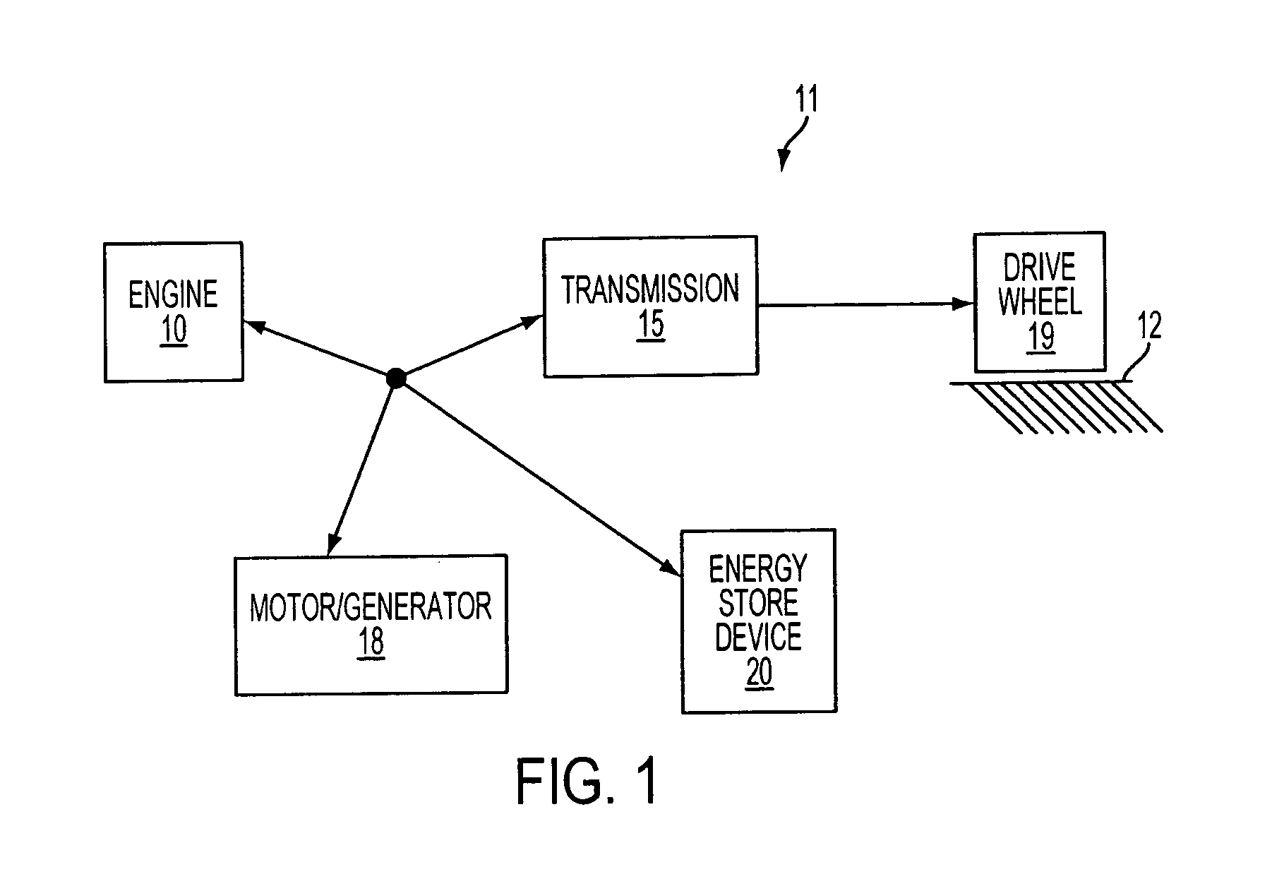
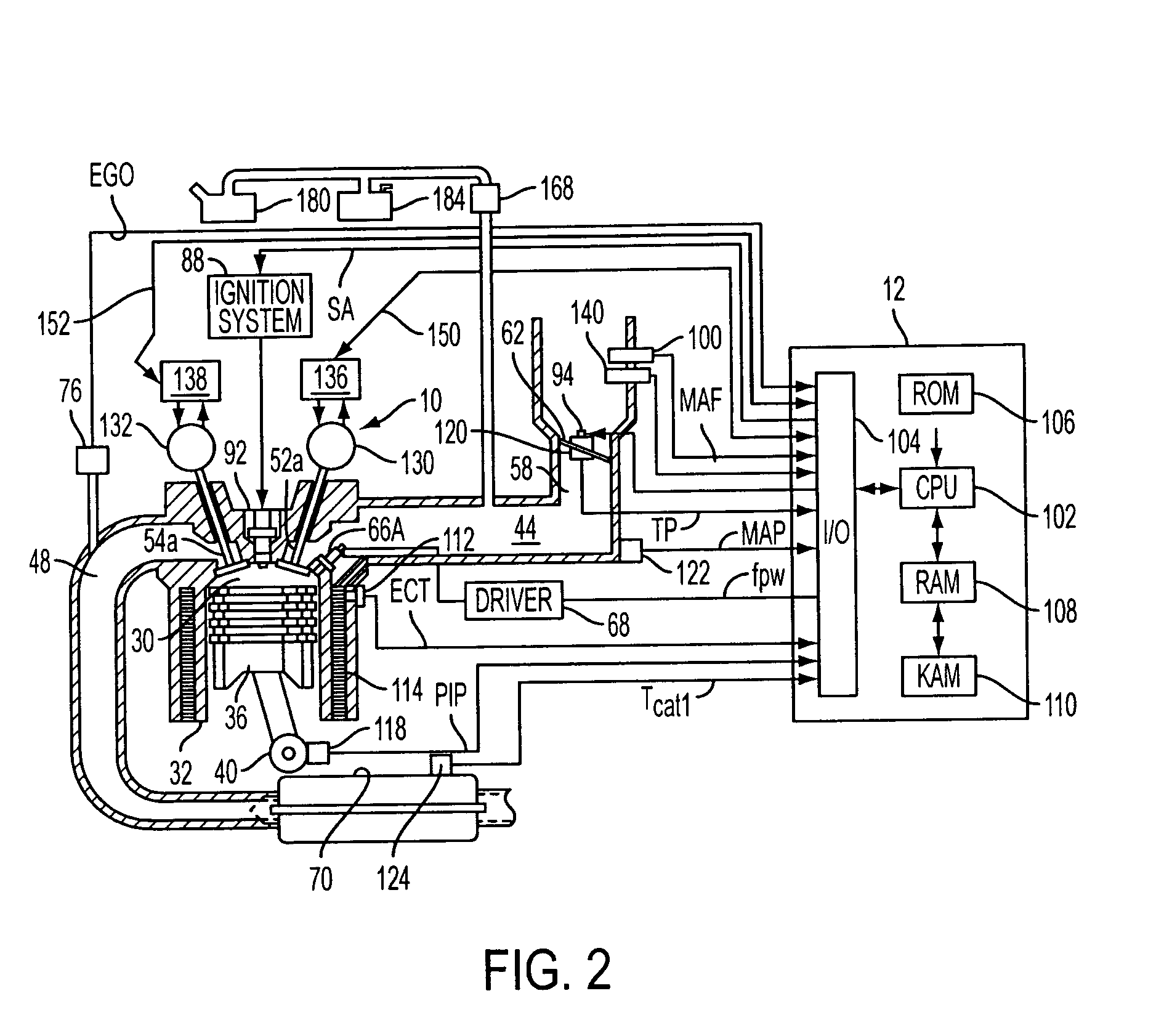
[0015] The present application relates to operation of an engine having adjustable intake and exhaust valve operation in a hybrid propulsion system. While adjustable engine valve timing operation may be used to obtain various advantages in a hybrid propulsion system, there are numerous constraints that have limited different performance aspects of hybrid propulsion systems.

[0016] As one example, an Atkinson cycle may be used to provide improved fuel economy and performance when matched with a hybrid propulsion system, however, the Atkinson cycle may result in degraded peak torque output at low to mid speeds, thus potentially reducing vehicle performance under some conditions, such as low battery state of charge. Further, the poor torque response may lead to secondary problems with NVH and efficiency because a higher RPM is required to produce sufficient power in real customer driving. One example of an Atkinson engine cycle is where fairly late intake valve closing (IVC) timing is ...


PUM


Abstract

A system for a vehicle with an engine having at least one cylinder with at least an intake valve and an exhaust valve, comprising of a hydraulic variable valve actuator system configured to vary a timing of the intake valve in a first range and a timing of the exhaust valve in a second range, said actuator system configured to have a default intake valve timing to which intake valve timing is held when insufficient hydraulic pressure is available to move intake valve timing, and a default exhaust valve timing to which exhaust valve timing is held when insufficient hydraulic pressure is available to move exhaust valve timing, where said default intake valve timing is in a retarded portion of said first range and said default exhaust valve timing is in a retarded portion of said second range, and a hybrid propulsion system coupled to the engine.

Description

BACKGROUND AND SUMMARY [0001] Engines have used various forms of variable cam timing to improve engine operation over a variety of speed / load conditions. Variable cam timing adjusts the relative timing of the camshaft to the crankshaft, thus changing valve opening / closing timing relative to piston movement. [0002] One type of variable cam timing system utilizes hydraulic oil pressure to adjust an actuator between the camshaft and crankshaft. For example, hydraulic vane type actuators may be used to move cam timing relative to crankshaft timing and piston position. The hydraulic actuator uses pressurized engine oil available during engine operation. However, when oil pressure is not available, a biasing spring and locking pin hold the actuator, and thus cam timing, in a default position, typically base timing which is in the earliest timing of the timing range. [0003] However, the inventors herein have recognized several issues with such approaches. For example, there may be conflict...

Claims


Application Information

Patent Timeline
Patent Type & Authority Applications(United States)
IPC IPC(8): F01L9/02F01L1/34F01L9/10F01L9/11
CPCB60K6/24Y02T10/18B60W10/06B60W20/00F01L1/053F01L1/34F01L1/3442F01L9/02F01L9/021F01L13/0015F01L2001/0535F01L2001/0537F01L2001/34453F01L2800/00F01L2800/06F01L2800/08F01L2800/12F02D13/0211F02D13/0219F02D13/06F02D41/08F02D2013/0292F02D2041/001F02M25/0752F02M25/089Y02T10/6221Y02T10/6295B60K6/48F02M26/01Y02T10/12Y02T10/62F01L9/11F01L9/10B60W20/15B60W10/08
Inventor LEONE, THOMAS G.
Owner FORD GLOBAL TECH LLC
Learn More