
System and method for automatic measurements and calibration of computerized magnifying instruments

a technology applied in the field of automatic measurement and calibration of computerized magnifying instruments, can solve the problems of complex nature of calibration parameters, and achieve the effects of less prone to errors, less variable calibration, and simplified calibration process for users

Active Publication Date: 2007-09-13
CLEMEX TECH
View PDF42 Cites 60 Cited by
  • Summary
  • Abstract
  • Description
  • Claims
  • Application Information

AI Technical Summary

Benefits of technology

[0006] The present invention aims at overcoming some of the drawbacks of present magnifying measurement systems such as microscopic imaging systems by providing systems and methods where calibration and specimen analysis is performed automatically, without user intervention. The present invention also automatically validates its own calibration, also without user intervention. This additional validation steps makes the method more robust and less prone to errors. The benefits of the present invention are the automatic production of repeatable and less variable calibration parameters, a simplification of the calibration process for the user, a reduction, and possibly elimination, of the number of specimen slide manipulations. The method minimizes the uncertainties of the calibration procedure and therefore improves the reliability of quantitative magnifying imaging systems used as digital measurement instruments. These are all elements that are expected to lead to a broader adoption and a wider use of computerized quantitative magnifying measurement systems.

Problems solved by technology

The nature of the calibration parameters can be quite complex, as their purpose is to compensate for all types of deformations and inhomogeneities induced by the entire imaging system, including non-linear effects due to all the optical / photoelectronic sub-components.
The complexity of these procedures is a factor that prevents a broader adoption of computerized magnifying measurement systems, as they are still considered as complex and sophisticated tools that require a dedicated technical expertise to be properly operated.

Method used


Image

  • System and method for automatic measurements and calibration of computerized magnifying instruments
  • System and method for automatic measurements and calibration of computerized magnifying instruments
  • System and method for automatic measurements and calibration of computerized magnifying instruments

Examples


Embodiment Construction

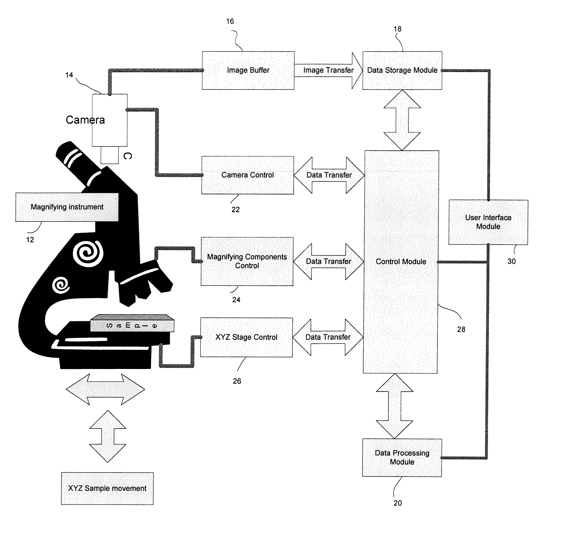
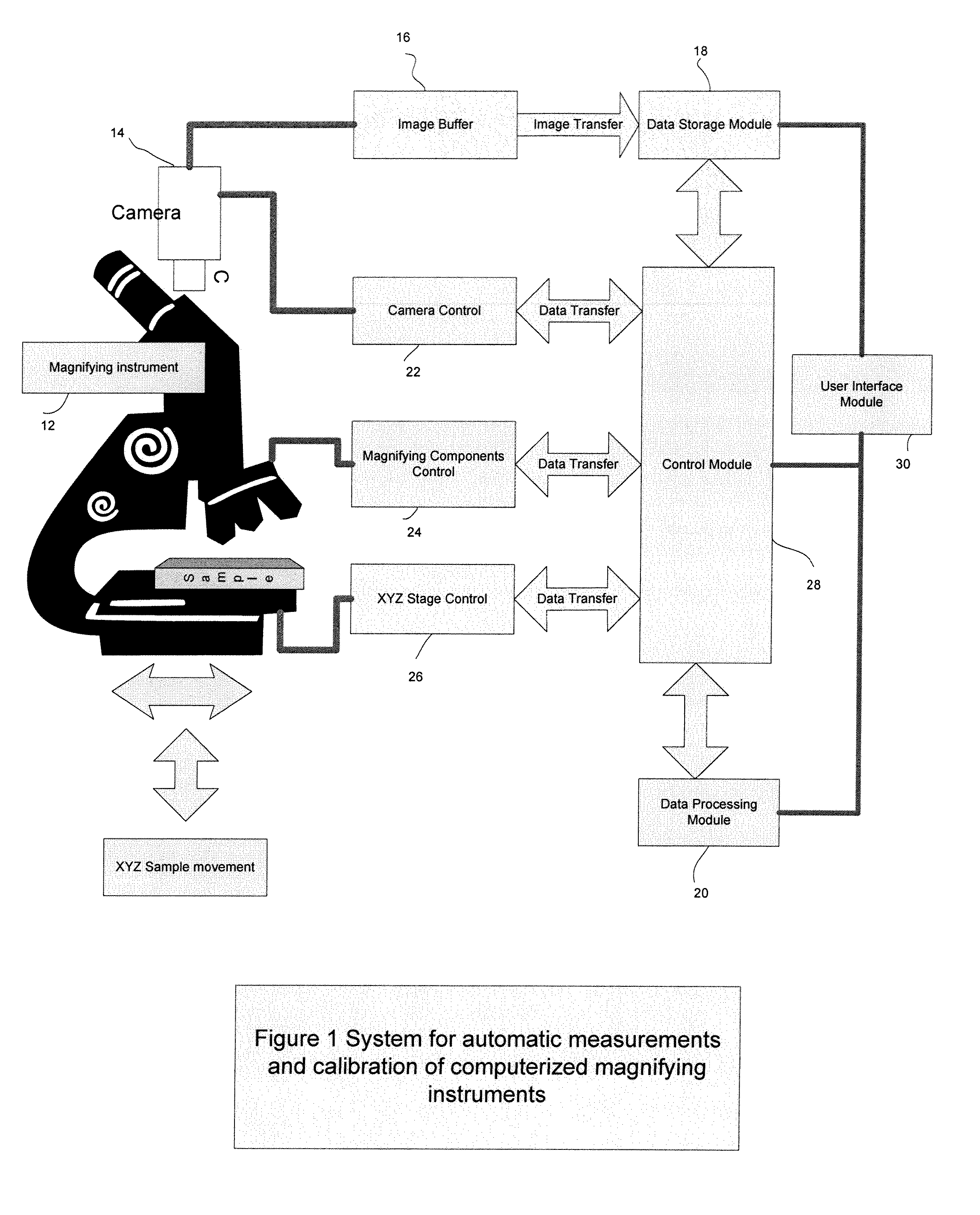
[0022] The present invention relates to a method and apparatus for measurements of objects attributes using a computerized magnifying measurement system such as a microscope.

[0023] In one aspect of the invention the system is calibrated automatically, that is to say substantially without user intervention thereby eliminating calibration errors introduced by user manipulations and subjectivity.

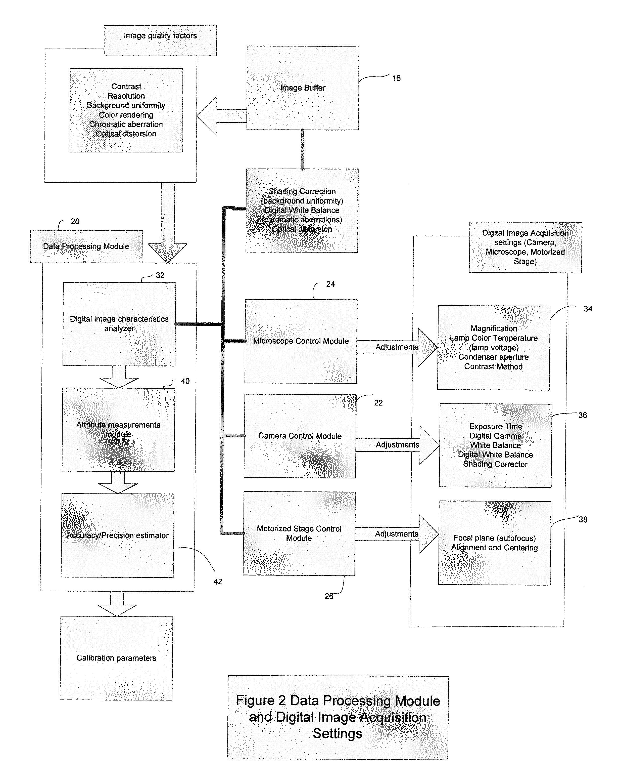
[0024] The calibration begins by obtaining an optimized digital image of an object comprising standardized landmark features. The dimensions of the standardized landmark features on a reference slide, traceable to real physical dimensions obtained from a standardized external measurement process, are archived in a database. The database contains an entry for each unique reference slide identified by a unique Serial Number. The serial number itself is recognized by the computerized imaging system to ensure the traceability of the calibration process The digital image is then automatically proc...


PUM


Abstract

The present invention relates to a system and method for automatic measurements and calibration of computerized magnifying instruments. More particularly, the method includes an automatic calibration aspect, which includes obtaining an optimized digital image of a reference object including at least one standardized landmark feature, and establishing calibration parameters based on one or more measured attributes of the landmark feature. The method further desribes a calibration aspect, which includes providing calibration parameters, obtaining a digital image including at least one known attribute, measuring the at least one known attribute and comparing the measured value with the known value. The method further includes an aspect of automatic measurement of an attribute of one or more object, which includes retrieving calibration parameters, acquiring a digital image and measuring the attribute. The system includes an object support, a reference object including one or more standardized landmark features, and an automatically readable identification means.

Description

CROSS-REFERENCE TO RELATED APPLICATION [0001] This application claims priority from U.S. provisional application No. 60 / 781,335 filed Mar. 13, 2006 entitled System and Method for Automatic Measurements and Calibration of Computerized Magnifying Instruments.FIELD OF THE INVENTION [0002] The invention relates to automatic measurements, calibration and validation of computerized magnifying instruments. BACKGROUND OF THE INVENTION [0003] Magnifying systems such as microscopic imaging systems are commonly used for conducting research, quantitative characterization and screening in various applications, such as semi-conductors fabrication, pharmaceutical research, biomedical and biotechnology laboratories, aerospace and automotive parts manufacturing. The measurements of attributes characterizing the elements present in microscopic images, finds applications in materials science and in pharmaceutical and biotechnological research. In order to compute accurately and precisely such attribut...

Claims


Application Information

Patent Timeline
Patent Type & Authority Applications(United States)
IPC IPC(8): G01J1/10
CPCG01B9/04G02B21/365G06T2207/30204G06T7/0018G06T2207/10056G02B27/0025G06T7/80
Inventor LAROCHE, SYLVAINFORGET, CLEMENT
Owner CLEMEX TECH
Learn More