System analysis apparatus and method

a system analysis and system analysis technology, applied in the field of system analysis apparatus and system analysis method, can solve the problems of increasing processing load, no commercially available products for packet capture processing, and difficulty in directly capturing packets using a single system analysis apparatus

Inactive Publication Date: 2007-09-13
FUJITSU LTD
View PDF8 Cites 19 Cited by
  • Summary
  • Abstract
  • Description
  • Claims
  • Application Information

AI Technical Summary

Benefits of technology

[0024] An object of the present invention is to solve the above-described problems, and provide a technique for performing system analysis on a multi-tiered server system which enables syst

Problems solved by technology

In systems where communication speeds exceed 1 Gbps, it is difficult to directly capture packets using a single system analysis apparatus.
In addition, there are no commercially available products for packet capturing processing which have capturing capabilities in excess of 1 Gbps.
While this method results in an increase in processing load, the method is effective if it is desi

Method used


Image

  • System analysis apparatus and method
  • System analysis apparatus and method
  • System analysis apparatus and method

Examples


first embodiment

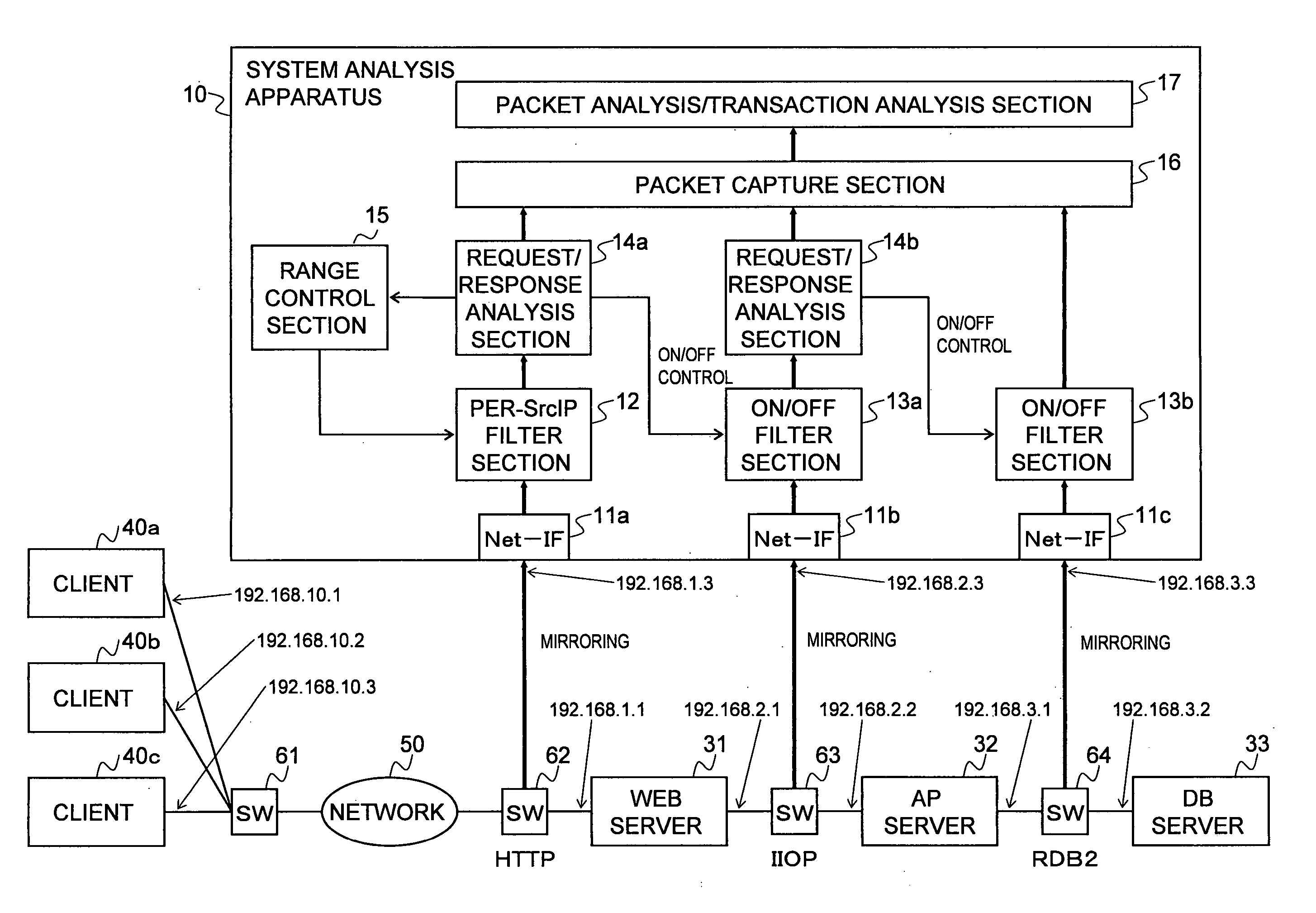
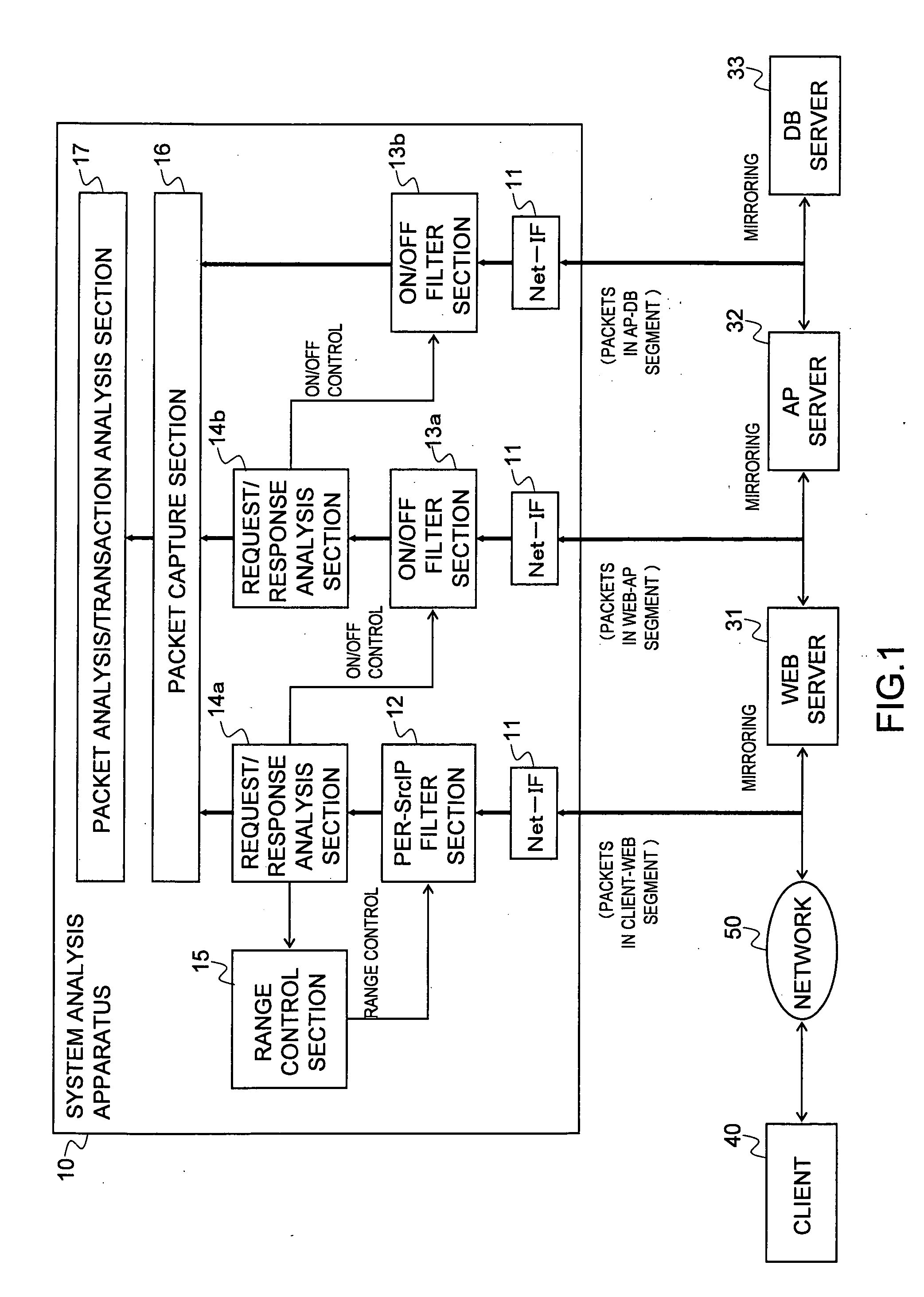
[0077]FIG. 4 is a diagram showing an example of a system analysis apparatus according to a first embodiment of the present invention. The present embodiment is an embodiment in which mirrored outputs of switches (SWs) 62, 63 and 64 placed in the communication path of each segment are inputted to different network interfaces (Net-IFs) 11a, 11b and 11c of a system analysis apparatus 10. The present embodiment corresponds to the above-described first principle.

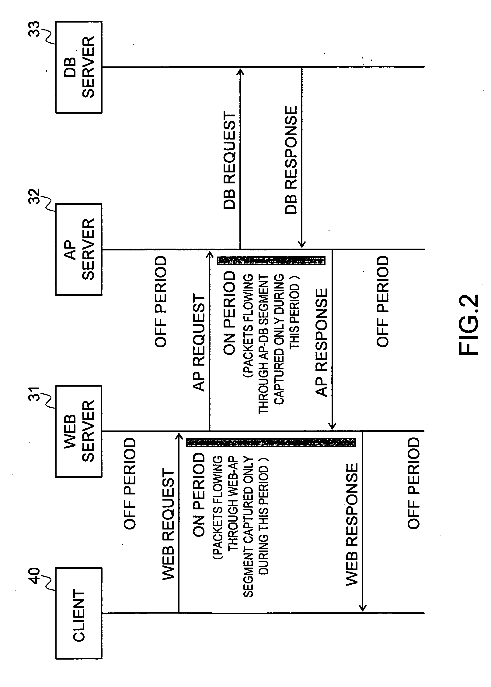
[0078] The system analysis apparatus 10 comprises Net-IF section 11s (11a, 11b and 11c), a per-SrcIP filter section 12, ON / OFF filter sections 13 (13a, 13b), request / response analysis sections 14 (14a, 14b), a range control section 15, a packet capture section 16, and a packet analysis / transaction analysis section 17. In the present embodiment, system analysis will be performed on a three-tiered server system consisting of a Web server 31, an AP server 32 and a DB server 33. In the present first embodiment, three clients 40 (40a...

second embodiment

[0114]FIG. 13 is a diagram showing an example of a system analysis apparatus according to a second embodiment of the present invention. The present embodiment is an embodiment in which mirrored outputs of switches (SWs) 62, 63 and 64 placed in the communication path of each segment are inputted to a single network interface Net-IF 11 of a system analysis apparatus 20. The present embodiment corresponds to the above-described second principle.

[0115] The system analysis apparatus 20 comprises the Net-IF 11, a per-SrcIP filter section 12, ON / OFF filter sections 13 (a, b), request / response analysis sections 14 (a, b), a range control section 15, a packet capture section 16, a packet analysis / transaction analysis section 17, and a segment separation section 18. Compared to the system analysis apparatus 10 of the first embodiment, the number of Net-IF sections 11 has been reduced from three to one and a segment separation section 18 has been newly added for the configuration of the syste...


PUM


Abstract

In a system analysis apparatus, a per-SrcIP filter section captures packets in client-Web server segments on a per-SrcIP basis. An ON/OFF filter section allows captured packets to pass through only when its flag is set to “ON”. A request/response analysis section controls a flag of the ON/OFF filter section of the next segment so that the packets of the next segment are captured only when the present segment is in a response waiting statue. A range control section controls a SrcIP range of packets to be captured by the per-SrcIP filter section.

Description

CROSS-REFERENCE TO RELATED APPLICATIONS [0001] This application claims priority from Japanese patent application Serial no. 2006-065446 filed Mar. 10, 2006, the contents of which are incorporated by reference herein. BACKGROUND OF THE INVENTION [0002] 1. Field of the Invention [0003] The present invention relates to a system analysis apparatus and a system analysis method for capturing flowing packets and performing transaction analysis in a multi-tiered server system connected to a high-speed network which exceeds, for instance, 1 Gbps (Giga bit per second). A multi-tiered server system is, for instance, a system in which servers configured in three tiers, namely a Web server, an application server (AP server) and a database server (DB server), perform predetermined processing by distributing the processing among the tiers. [0004] 2. Description of the Related Art [0005] In a multi-tiered server system, system performance is analyzed by capturing flowing packets, performing packet ...

Claims


Application Information

Patent Timeline
IPC IPC(8): G06F15/173G06F13/00H04L12/70
CPCH04L69/22H04L67/32H04L67/60
Inventor KURITA, TOSHIHIKO
Owner FUJITSU LTD
Why Eureka
Try Eureka