Method for Fabricating an Optical Fiber, Preform for Fabricating an Optical Fiber, Optical Fiber and Apparatus

a technology of preform and optical fiber, which is applied in the direction of manufacturing tools, mechanical equipment, instruments, etc., can solve the problems of continuous concern for the cost of high-quality optical fiber from rod-and-tube preform production, negative effect on productivity, and inability to make preforms of more than 25 mm in diameter, etc., to achieve high flexibility, reduce breakage risks, and increase the effect of drawing for

Active Publication Date: 2007-09-20
SILITEC
View PDF14 Cites 27 Cited by
  • Summary
  • Abstract
  • Description
  • Claims
  • Application Information

AI Technical Summary

Benefits of technology

[0037] The overcladding grain may be a pure or doped synthetic silica powder that may be selected according to the desired properties of the fabricated fiber. A method of manufacturing a silica powder using a solgel technique is described in [6], U.S. Pat. No. 6,047,568. Further solgel techniques, for achieving higher drawing forces and reducing breakage risks during the drawing process are described in [7], U.S. Pat. No. 6,334,338. Hence the inventive method also provides a high flexibility that allows meeting the customer's demands within short notice.

Problems solved by technology

As further stated in [2], the MCVD method, used by itself, has the inherent limitation that it is not suitable to make preforms of more than 25 mm in diameter.
In [2], it has been found that carrying out these three steps separately requires a) substantial amounts of time and consequently has a negative effect on productivity; b) a large amount of oxygen or hydrogen for the step of overcladding the primary optical fiber preform; and c) application of a relatively large amount of heat for the overcladding step, if the primary optical fiber preform is relatively large.
One problem in combining the fusing and drawing stages has been to control the application of vacuum with sufficient precision that the finished optical fiber has sufficient strength and optical quality for modern communications applications.
However, besides these known main concerns, costs for the production of high quality optical fiber from a rod-and-tube preform are a continuous concern.

Method used


Image

  • Method for Fabricating an Optical Fiber, Preform for Fabricating an Optical Fiber, Optical Fiber and Apparatus
  • Method for Fabricating an Optical Fiber, Preform for Fabricating an Optical Fiber, Optical Fiber and Apparatus
  • Method for Fabricating an Optical Fiber, Preform for Fabricating an Optical Fiber, Optical Fiber and Apparatus

Examples


Embodiment Construction

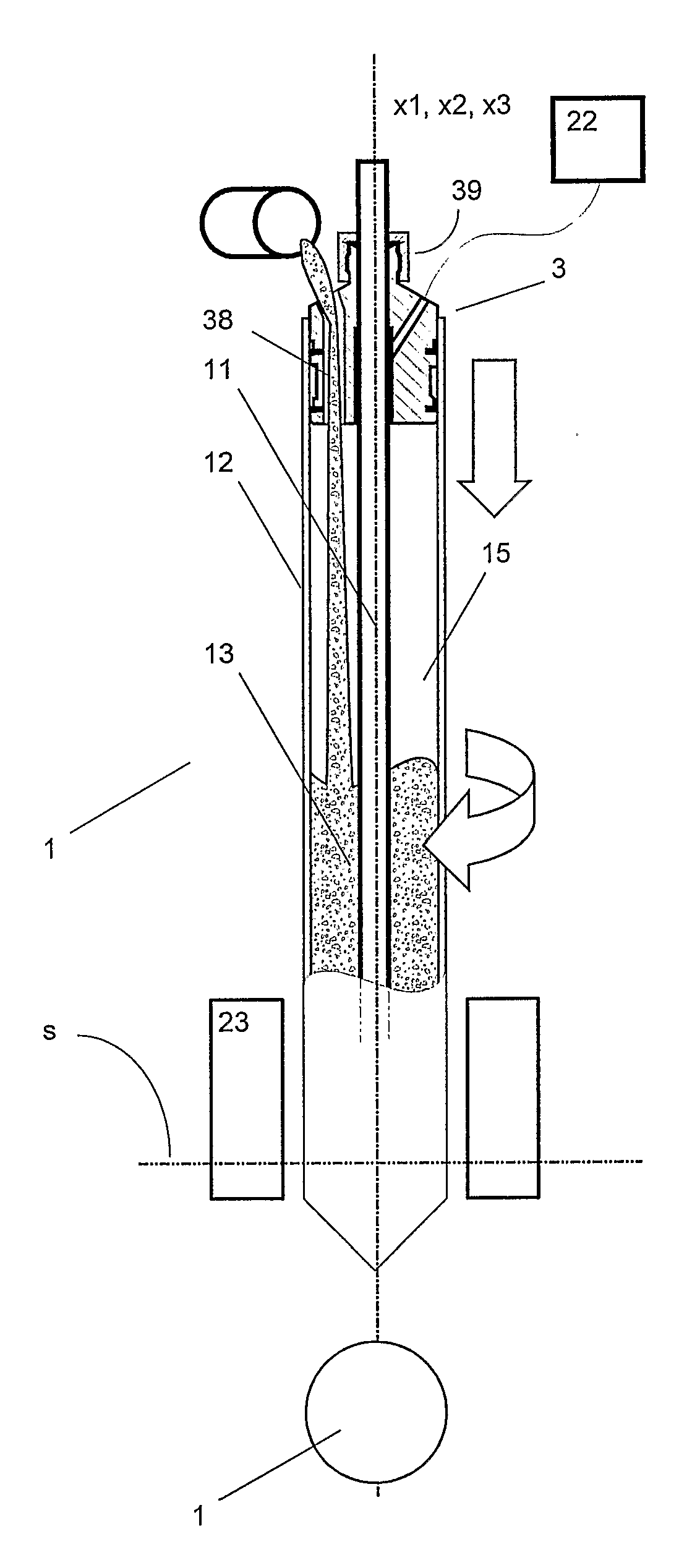
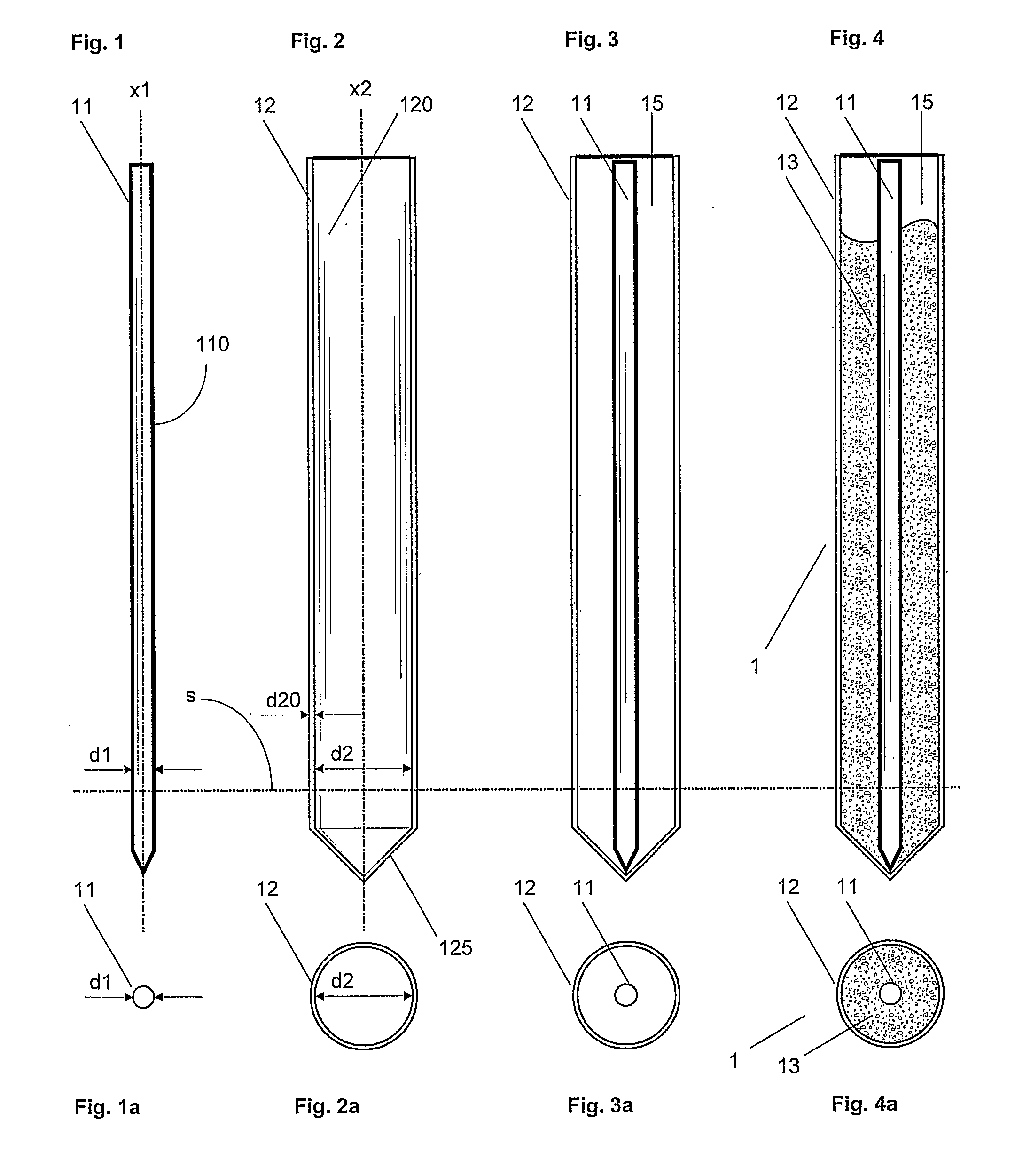
[0049]FIG. 1 shows a primary preform 11 having a first primary axis x1, an outer diameter d1 and an outer surface 111. Manufacturing of such a preform has been described above.

[0050]FIG. 2 shows a thin walled silica tube 12, having a first primary axis x2, an inner diameter d2, an outer diameter d20 and an inner surface 120. The thin walled silica tube 12, which comprises a conical closure 125 at its lower end, is used according to the inventive method as overcladding tube 12. Silica tubes of this kind are available from several manufacturers.

[0051]FIG. 3 shows the primary preform 11 held in a centrally inserted position within the overcladding tube 12 with said first and second primary axes x1, x2 in substantial alignment with each other.

[0052] The diameter d20 of the circular wall of the overcladding tube 12 is for example ten times smaller than its inner diameter d2. However the ratio of said diameters d2 / d20 may be up to 50 and higher. The ratio d2 / d1 of the inner diameter d2...


PUM

PropertyMeasurementUnit
temperatureaaaaaaaaaa

Abstract

The method for fabricating an optical fiber comprises the steps of inserting a primary optical fiber preform (11) having a first primary axis (x1) and an outer surface (111) into an overcladding tube (12) having a second primary axis (x2) and an inner surface (120), so that said outer surface and inner surface define an interior space (15); holding the primary preform (11) in a centrally inserted position within the overcladding tube (12) with said first and second primary axes (x1, x2) in substantial alignment with each other; supplying overcladding grain (13) into the interior space (15) that is limited at the lower end of the overcladding tube (12) by means of a closure (125); generating a condition of reduced pressure within the interior space (15) that is limited at the upper end of the overcladding tube (12) by means of an adjoiner (3), which holds the primary optical fiber preform (11) and the overcladding tube (12) in position; and heating the unprocessed secondary preform (1), that consists of the primary preform (11), the overcladding tube (12) and the overcladding grain (13), at its lower end to a softened state and simultaneously or subsequently drawing an optical fiber therefrom.

Description

[0001] The present invention relates to a method and an apparatus for fabricating an optical fiber and to a preform used for fabricating an optical fiber as well as to optical fiber fabricated according to said method. [0002] Fabrication of optical fibers, such as the fibers currently used in ultra high speed data communication networks, is described in [1], Mool C. Gupta, Handbook of PHOTONICS, CRC Press, 1997 Boca Raton, chapter 10.7, pages 445-449. Main process steps of optical fiber fabrication are fabricating a glass blank (below called preform), drawing the fiber from the preform and coating the fiber with a material that protects the fiber from handling and from environmental influences. [0003] According to [1], there are basically three methods to form the preform. The modified chemical vapor deposition process (MCVD), the outside vapor deposition process (OVD) and the vapor axial deposition process (VAD). [0004] In the drawing process, the preform is fed from above into the...

Claims


Application Information

Patent Timeline
Patent Type & Authority Applications(United States)
IPC IPC(8): C03B37/02C03B37/012C03B37/027
CPCC03B37/01211C03B37/02736C03B2205/13C03B2205/08C03B37/02754Y02P40/57G02B6/00C03B37/012
Inventor PEDRIDO, CARLOS
Owner SILITEC
Why Eureka
Try Eureka