Motor

a motor and stator technology, applied in the field of motors, can solve the problems of inability to mount the motor on an apparatus that requires miniaturization, the output torque in comparison with the dimension of the motor b>1/b> becomes undesirable, and the overall length of the motor is short, so as to increase the output torque, shorten the overall length of the motor, and increase the size of the stator portion

Inactive Publication Date: 2007-09-20
SANKYO SEIKI MFG CO LTD
View PDF11 Cites 16 Cited by
  • Summary
  • Abstract
  • Description
  • Claims
  • Application Information

AI Technical Summary

Benefits of technology

[0008]In view of the problems described above, an embodiment of the present invention advantageously provides a motor which is capable of shortening the overall length of the motor or which is capable of increasing size of a stator portion in comparison with the overall length of the motor to increase an output torque in comparison with a dimension of the motor. Further, an embodiment of the present invention advantageously provides a motor in which a rotor shaft is pressurized not only in a thrust direction but in a radial direction to prevent occurrence of knocking noise generated between the rotor shaft and the bearing.

Problems solved by technology

There are, however, problems with the conventional motors discussed above.
Therefore, the bearing holder 7 becomes an obstacle when the motor 1 is mounted on an apparatus such as a camera and thus the motor 1 cannot be mounted on an apparatus that requires miniaturization.
Further, the size of the stator 5 occupying the overall length of the motor 1 becomes relatively small and thus an output torque in comparison with a dimension of the motor 1 becomes undesirably small.

Method used


Image

  • Motor
  • Motor
  • Motor

Examples


Embodiment Construction

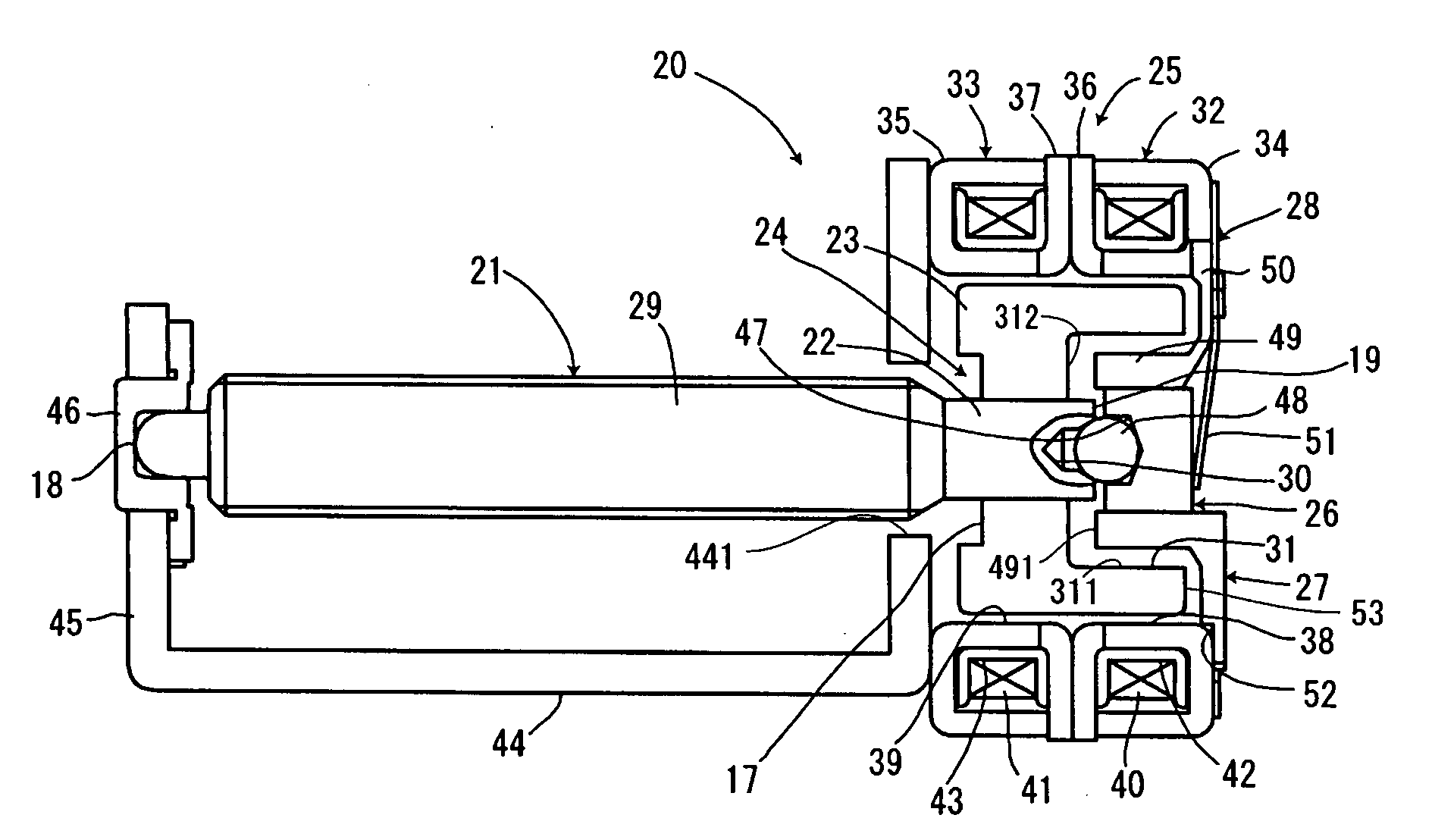
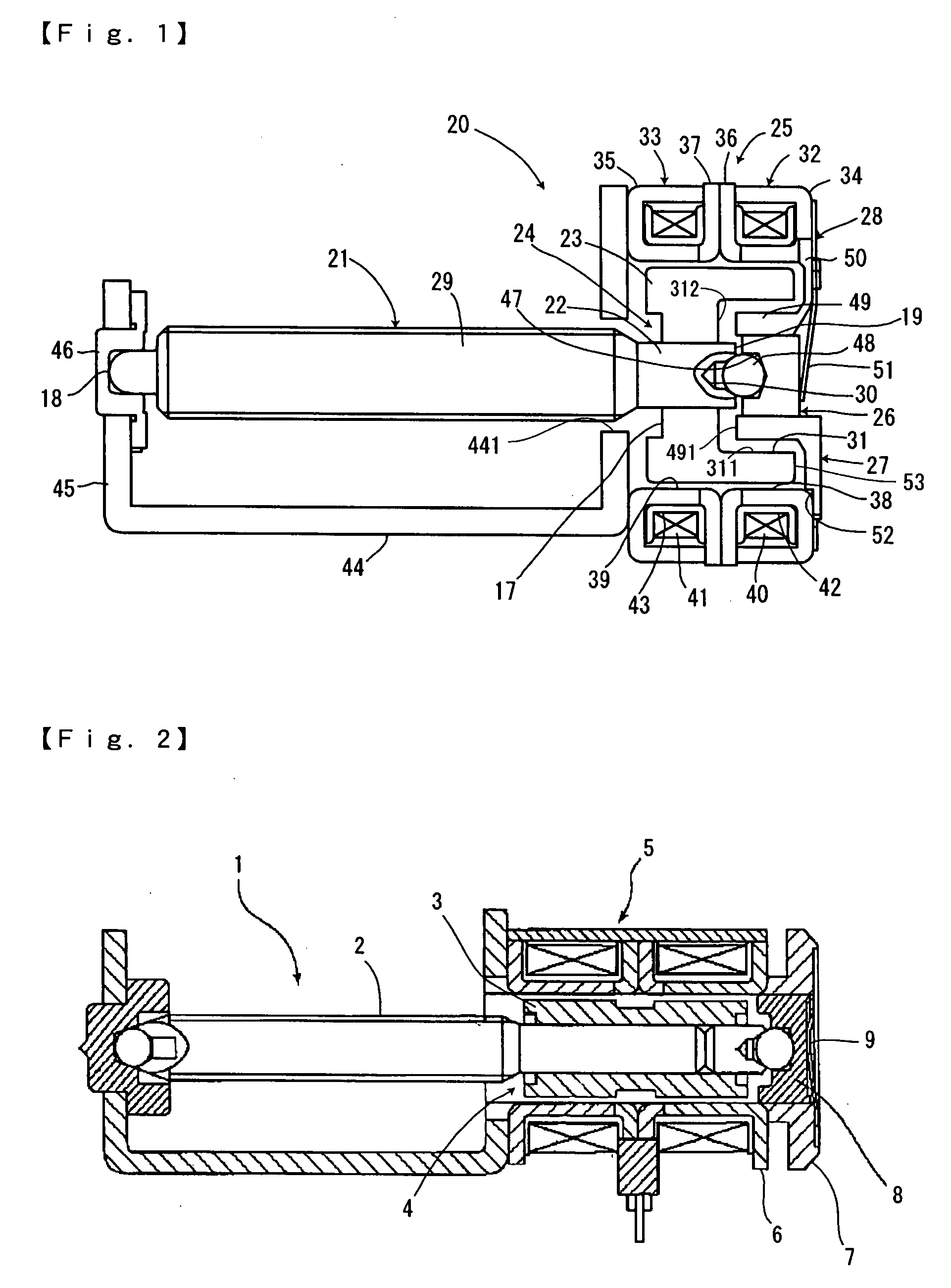
[0023]A motor in accordance with an embodiment of the present invention will be described below with reference to the accompanying drawings. FIG. 1 is a cross-sectional view showing a motor in accordance with an embodiment of the present invention. In this embodiment, the present invention is applied to a stepping motor but it is not limited to the stepping motor.

[0024]As shown in FIG. 1, a stepping motor 20 in accordance with an embodiment of the present invention includes a rotor 24 having a rotor shaft 21 and a permanent magnet 23 which is fixed to an end part 22 of the rotor shaft 21, a stator 25 which is disposed around the rotor 24, a slide bearing 26 for supporting an shaft end 19 of the rotor shaft 21, a bearing holder 27 which movably holds the slide bearing 26 in a thrust direction, and a pressurization apply member 28 which is provided on an outer side in an axial direction of the bearing holder 27.

[0025]An output shaft 29 protruding on the other side from the stator 25 i...


PUM


Abstract

A motor including a rotor having a rotor shaft and a permanent magnet fixed to an end part of the rotor shaft, a stator disposed around the rotor, a bearing for supporting the end part of the rotor shaft, a bearing holder which holds the bearing movably in an axial direction, and a pressurization member which is disposed on an outer side in the axial direction of the bearing holder for urging the bearing to the rotor shaft side. The permanent magnet is provided with a recessed part which is capable of accommodating the bearing and the bearing holder.

Description

CROSS REFERENCE TO RELATED APPLICATIONThe present invention claims priority under 35 U.S.C. §119 to Japanese Application No. 2006-73791 filed Mar. 17, 2006, which is incorporated herein by reference.FIELD OF THE INVENTION[0001]The present invention relates to a motor which may be used for driving a lens in a camera or the like and, more specifically, to a small motor which is provided with a bearing that is movable in a thrust direction.BACKGROUND OF THE INVENTION[0002]Small motors have been conventionally used for driving a lens of a digital camera and a video camera, and the like. It has been known to use a motor with a bearing which is movable in a thrust direction as well as a motor without a movable bearing.[0003]A conventional motor 1 is shown in FIG. 2. Referring to FIG. 2, a stator 5 is disposed around a rotor 4 having a permanent magnet 3 which is fixed to a rotor shaft 2, and a bearing holder 7 is fixed to a metal case 6 of a stator 5 so as to be protruded on an outer side...

Claims


Application Information

Patent Timeline
Patent Type & Authority Applications(United States)
IPC IPC(8): H02K37/14H02K5/16H02K1/12
CPCH02K1/27H02K7/083H02K5/1672
Inventor AGEMATSU, IKUO
Owner SANKYO SEIKI MFG CO LTD
Why Eureka
Try Eureka