Whiskerless plated structure and plating method

Active Publication Date: 2007-09-20
FUJITSU LTD
View PDF2 Cites 23 Cited by
  • Summary
  • Abstract
  • Description
  • Claims
  • Application Information

AI Technical Summary

Benefits of technology

[0023] According to the above-described structure and method, whiskerless tin-based plating with a s

Problems solved by technology

Tin whiskers often cause electric failure or short-circuiting between adjacent electrodes.
The dispersed whiskers cause further problems, including short-circuiting, in and outside devices.
However, the method of forming a diffusion barrier film causes another problem because a nickel plating f

Method used


Image

  • Whiskerless plated structure and plating method
  • Whiskerless plated structure and plating method
  • Whiskerless plated structure and plating method

Examples


Embodiment Construction

[0030] The preferred embodiments of the present invention are described below with reference to the attached drawings.

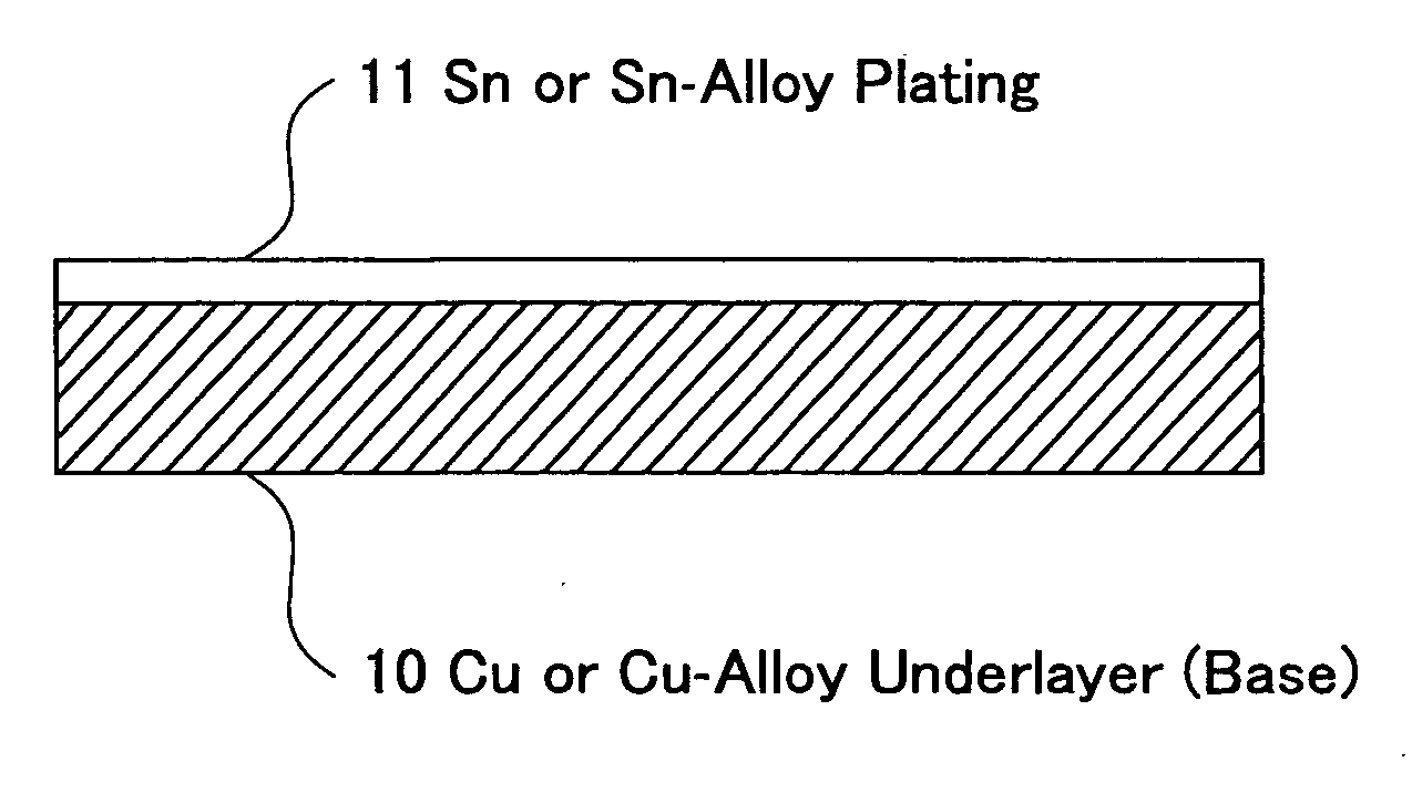
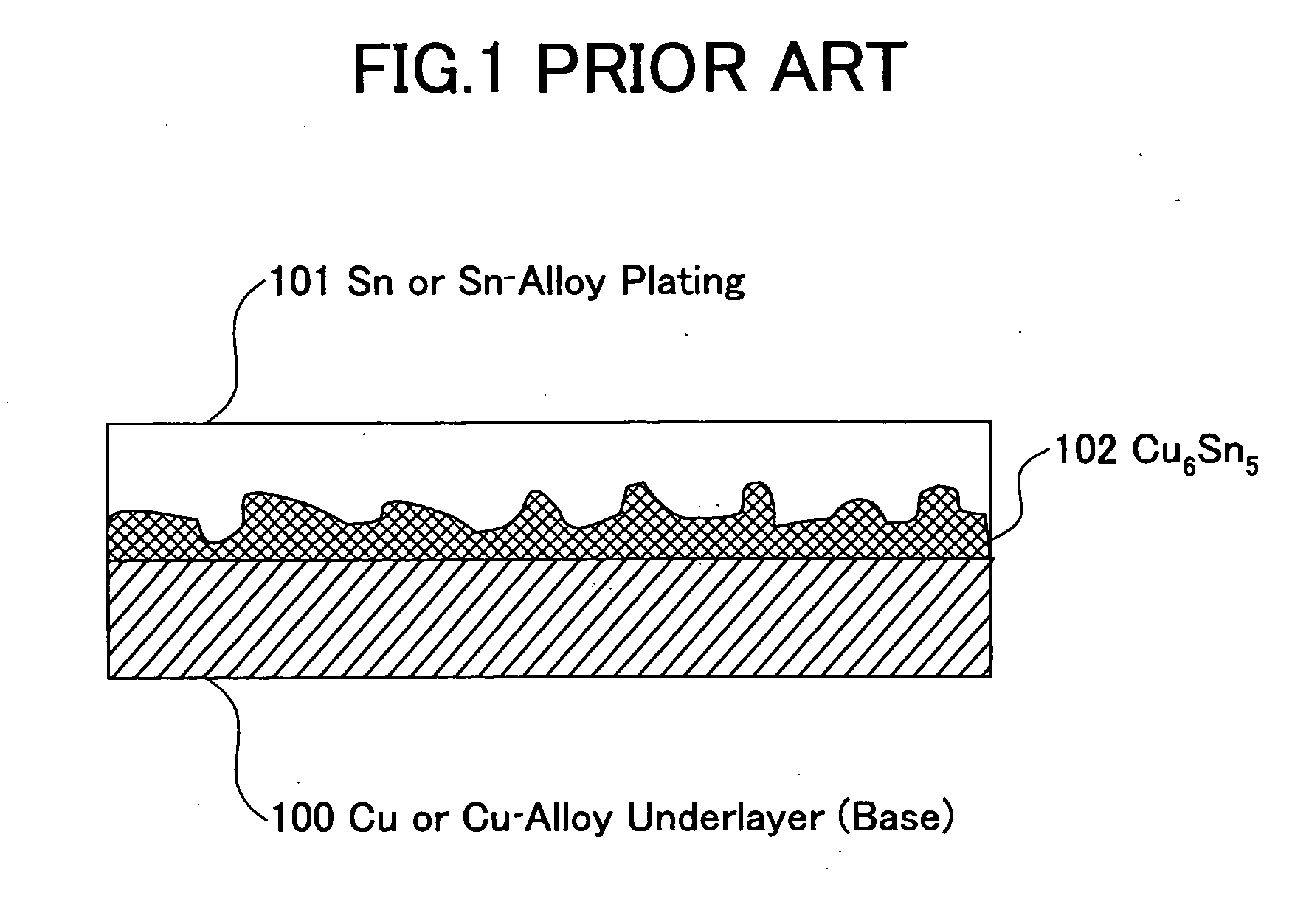
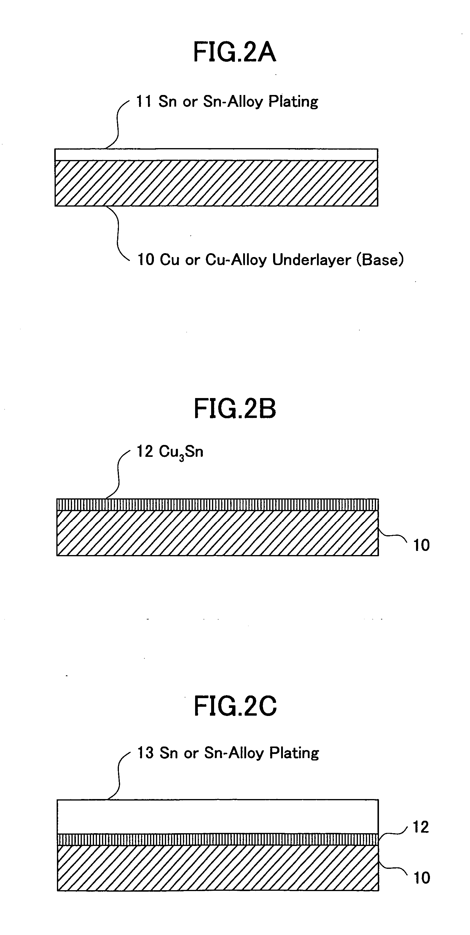
[0031]FIG. 2A through FIG. 2C illustrate in cross-sectional views a whiskerless plating process, including formation of a tin-based plating film, according to an embodiment of the invention. In FIG. 2A, a first tin or tin-alloy plating film (which is referred to as a “tin-based plating film”) 11 is formed over a Cu or Cu-alloy base 10. The base 10 actually used in the experiment is a connector terminal of a 40-pin connector made of phosphor bronze. Prior to the tin-based plating, cathode electrolytic degreasing is performed as pretreatment on the base 10. The electrolytic degreasing agent is, for example, Cleaner 160 manufactured by Meltex Co., Ltd. In the embodiment, the pretreatment temperature is 65° C., the electric current density is 2.5 A / dm2, and the pretreatment time is 30 seconds. After the electrolytic degreasing, the base 10 is rinsed by water.

[0032] The...


PUM

PropertyMeasurementUnit
Temperatureaaaaaaaaaa
Thicknessaaaaaaaaaa

Abstract

A plated structure is disclosed that includes a base formed of a copper-based material containing copper as a major component, a plating film formed of a tin-based material containing tin as a major component and provided over the base, and a tin-copper compound barrier film located at the boundary between the base and the plating film. The density of the tin-copper compound barrier film is greater than that of copper.

Description

BACKGROUND OF THE INVENTION [0001] 1. Field of the Invention [0002] The present invention generally relates to a plating technique, and more particularly, to a whiskerless and lead-free plated structure and plating method involving the formation of a tin-based plating coating used in place of a tin-lead (Sn—Pb) plating film. [0003] 2. Description of Related Art [0004] Conventionally, tin-lead (Sn—Pb) solder plating is applied to metallic devices and components, such as connector terminals or lead frames for semiconductor integrated circuits. In recent years and continuing, however, lead-free plating has been discussed and studies are being conducted to perform lead-free plating in place of conventional tin-lead solder plating from the viewpoint of protection of the environment. Candidates for lead-free plating include leadless tin plating, tin-copper (Sn—Cu) alloy plating, tin-bismuth (Sn—Bi) alloy plating, and tin-silver (Sn—Ag) alloy plating. Japanese Patent Laid-Open Application ...

Claims


Application Information

Patent Timeline
IPC IPC(8): B32B15/01
CPCB32B15/015Y10T428/12715C22C13/00C22C13/02C23C18/1601C23C18/1651C23C18/1692C23C18/18C23C18/1848C23C18/48C23C18/52H01L2924/0002C22C9/02H01L2924/00C25D3/60
Inventor SAKUYAMA, SEIKISHIMIZU, KOZO
Owner FUJITSU LTD
Why Eureka
Try Eureka