
Magnetic recording medium, method of producing same, and magnetic storage apparatus

magnetic storage technology, applied in the field of magnetic recording medium, can solve the problems of difficult to improve the recording density of a magnetic recording medium using the longitudinal magnetic recording method, difficulty in maintaining sufficient recordability, and substantial risk in starting a full-scale mass production of such magnetic storage apparatus, and achieve excellent s/n ratio, high recording density, and in-plane orientation. good

Inactive Publication Date: 2007-09-20
SHOWA DENKO KK
View PDF4 Cites 19 Cited by
  • Summary
  • Abstract
  • Description
  • Claims
  • Application Information

AI Technical Summary

Benefits of technology

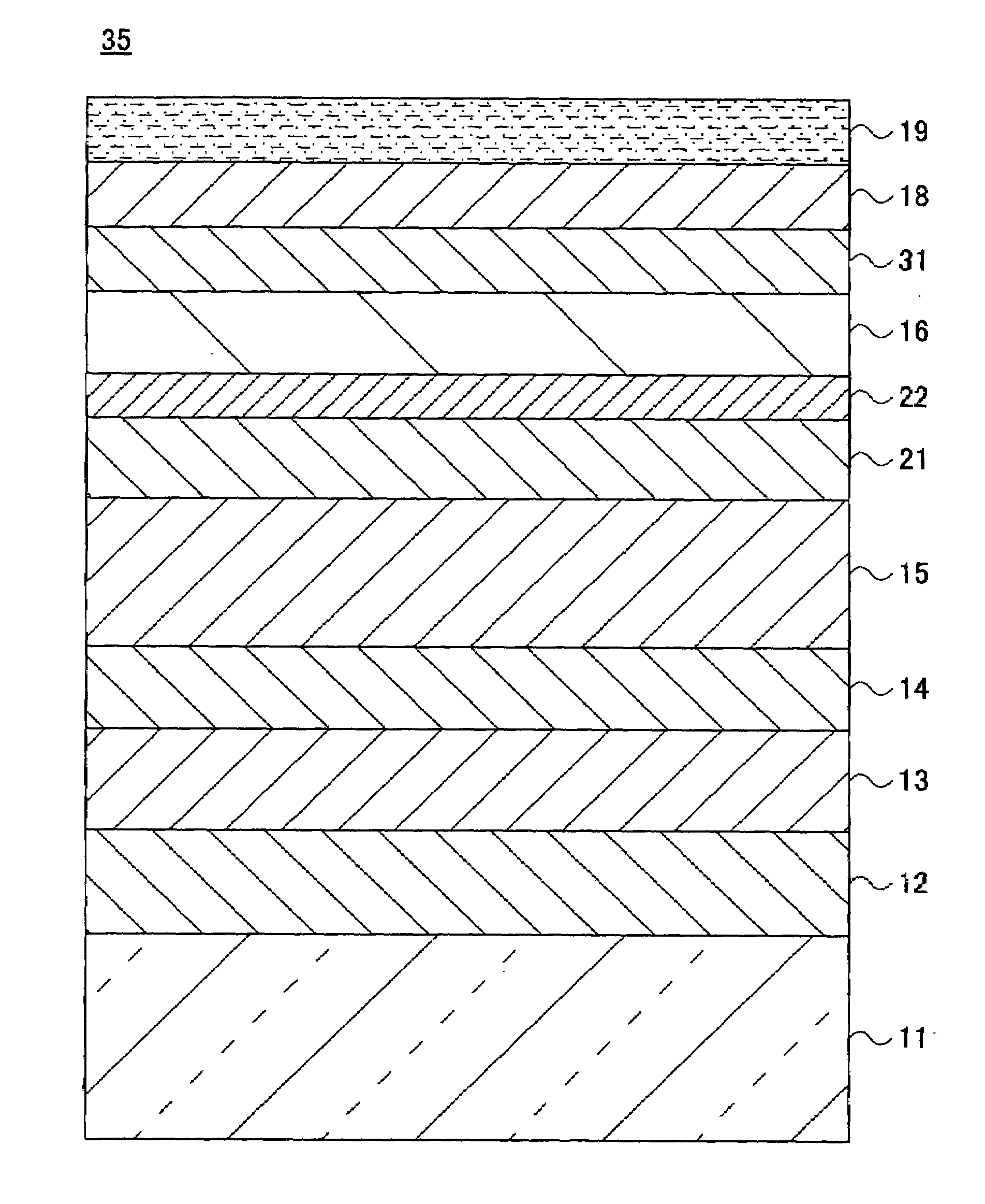
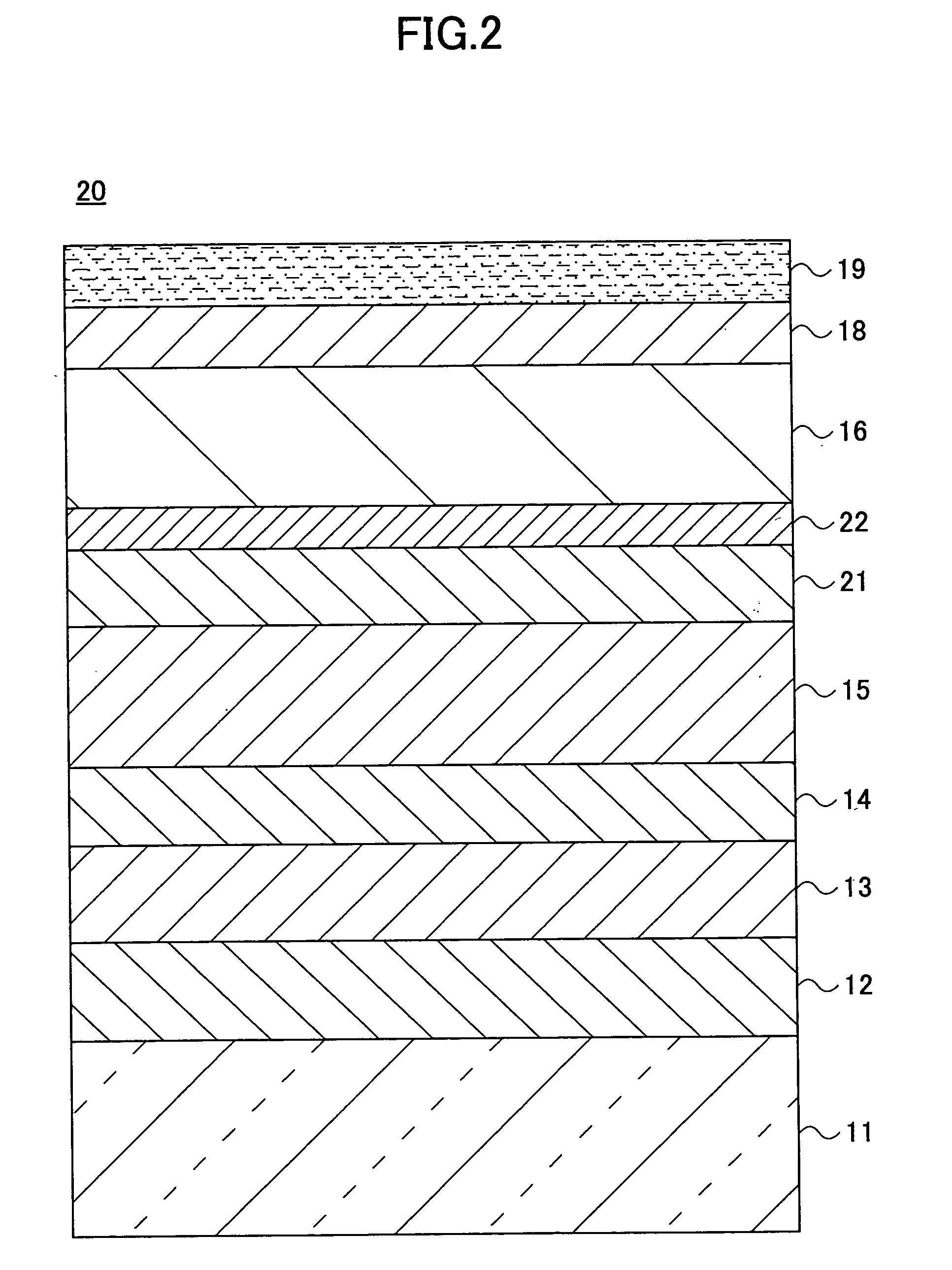
[0014]According to one aspect of the present invention, a magnetic recording medium includes an underlayer made of a material having a body-centered-cubic crystalline structure or a B2 crystalline structure, and serving as a base for a magnetic layer having a granular structure; a first intermediate layer having a hexagonal closest packing crystalline structure and made of Co or a Co alloy; a second intermediate layer having a hexagonal closest packing crystalline structure and made of a material selected from the group consisting of Ru, Ti, Re, Zr, Hf, and a Ru alloy. This configuration improves the in-plane orientation of the c axis of each magnetic grain having a hexagonal closest packing crystalline structure and improves the in-plane coercivity. As a result, a magnetic recording medium according to an embodiment of the present invention provides an excellent S / N ratio which is a feature of a magnetic layer having a granular structure. Such a magnetic recording medium provides an improved in-plane coercivity and in-plane orientation. The present invention makes it possible to provide a magnetic recording medium with an improved recording density. In this specification, an in-plane coercivity is a coercivity in a direction parallel to the surface of a substrate; and an in-plane orientation is a degree to which the c axis (axis of easy magnetization) of a magnetic grain is oriented in a direction parallel to the substrate surface.
[0016]A magnetic recording medium according to an embodiment of the present invention provides an excellent S / N ratio which is a feature of a magnetic layer having a granular structure. Such a magnetic recording medium provides an improved in-plane coercivity and in-plane orientation.
[0018]A magnetic recording medium according to an embodiment of the present invention provides an excellent S / N ratio, in-plane coercivity, and in-plane orientation. Such a magnetic recording medium enables production of a magnetic storage apparatus having a high recording density.
[0019]According to one aspect of the present invention, a magnetic recording medium includes an underlayer, as a base for a magnetic layer having a granular structure, made of a material having a body-centered-cubic crystalline structure or a B2 crystalline structure; a first intermediate layer having a hexagonal closest packing crystalline structure and made of Co or a Co alloy; a second intermediate layer having a hexagonal closest packing crystalline structure and made of a material selected from the group consisting of Ru, Ti, Re, Zr, Hf, and a Ru alloy. This configuration enables providing a magnetic recording medium having a high recording density. The present invention provides such a magnetic recording medium, a method of producing such a magnetic recording medium, and a magnetic storage medium having such a magnetic recording medium.

Problems solved by technology

However, because of concern about their reliability and high production costs, there is still a substantial risk in starting a full-scale mass production of such magnetic storage apparatuses.
The reasons making it hard to improve the recording density of a magnetic recording medium using the longitudinal magnetic recording method include the difficulty in maintaining sufficient recordability and in improving the signal-to-noise (S / N) ratio of a magnetic recording medium having an alloy recording layer using an alloy such as a CoCrPtB alloy.
Poor recordability may result from the lack of sufficient recording head magnetic field.
In other words, it is very difficult to make the switching magnetic field of magnetic grains comprising a recording layer smaller than the recording head magnetic field.
However, as the magnetic grain size decreases, the rate of decrease over time in remanent magnetization caused by thermal disturbance increases.
As a consequence, in a magnetic recording medium using an alloy recording layer, the switching magnetic field increases as the recording density increases, and maintaining recordability becomes difficult.
However, with a conventional granular medium, it is difficult to achieve a sufficient in-plane coercivity (coercivity in a direction parallel to the substrate surface) and a sufficient in-plane orientation (a degree to which the axis of easy magnetization of a magnetic grain is oriented in a direction parallel to the substrate surface) at the same time.
For this reason, further improving the recording density of a granular medium is difficult.

Method used


Image

  • Magnetic recording medium, method of producing same, and magnetic storage apparatus
  • Magnetic recording medium, method of producing same, and magnetic storage apparatus
  • Magnetic recording medium, method of producing same, and magnetic storage apparatus

Examples


first embodiment

1. First Embodiment

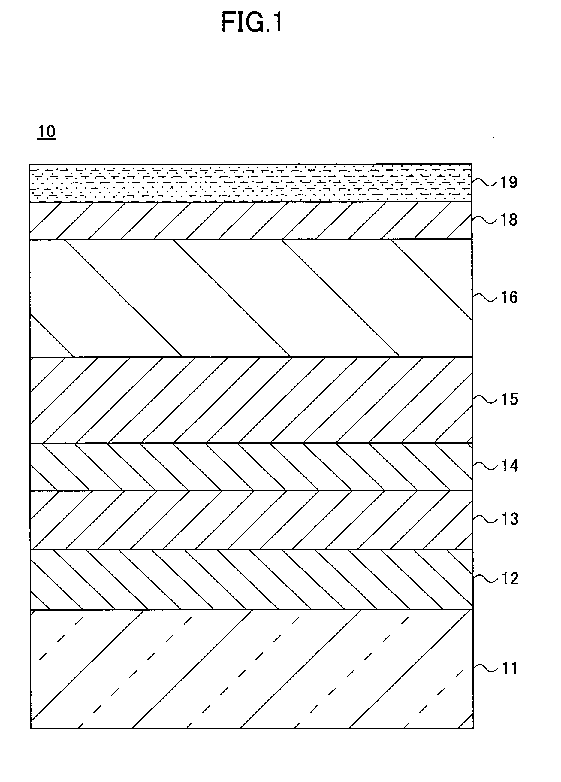
[0037]FIG. 1 is a cross-sectional view of a first exemplary magnetic recording medium according to the first embodiment of the present invention. As shown in FIG. 1, a first exemplary magnetic recording medium 10 has a structure in which a substrate 11, a seed layer 12, an underlayer 13, a first intermediate layer 14, a second intermediate layer 15, a magnetic layer 16, a protective film 18, and a lubrication layer 19 are disposed from bottom to top in the order mentioned.

[0038]For the substrate 11, materials including, for example, glass, NiP-plated aluminum alloy, silicon, plastic, ceramic, carbon may be used.

[0039]The surface of the substrate 11 may have a texture (a mechanical texture, for example) made up of multiple grooves along the recording direction (for example, the circumferential direction when the magnetic recording medium 10 is a magnetic disk). Such a texture assists orienting the c axis (axis of easy magnetization) of the magnetic layer 16 in the ...

examples 3 and 4

[0119]In examples 3 and 4, magnetic disks having magnetic layer thicknesses between 10 nm and 30 nm are produced and their in-plane coercivities and coercivity ratios are measured in a same manner as in example 1.

[0120]Magnetic disks in example 3 have a layer configuration where a substrate, a seed layer (CrTi film: 25 nm), an underlayer (AlRu film: 20 nm and CrMoTi film: 6 nm), a first intermediate layer (CO90Cr10 film: 1.5 nm), a second intermediate layer. (Ru film: 30 nm), a magnetic layer ((CoCrPt20)90—(SiO2)10 film: 15 nm), and a protective film (carbon film: 4.5 nm) are disposed from the bottom to the top in the order mentioned. Magnetic disks in example 4 have the same configuration as that in example 3, except that the material for the magnetic layer is (CoCrPt25)90—(SiO2)10. The deposition conditions in examples 3 and 4 are the same as those in example 1.

[0121]In the above description, figures in brackets (25 nm, for example) show thicknesses of corresponding layers. Thickn...

example 5

[0125]A magnetic disk in example 5 has the same layer configuration as that in example 3, except that the first intermediate layer is a pure Co film. The thickness of the pure Co film as the first intermediate layer is incremented by 0.5 nm within a range between 0.5 nm and 2.0 nm. The deposition conditions in example 5 are the same as those in example 1.

[0126]FIG. 8A is a graph showing a relationship between in-plane coercivities and Co film thicknesses of the magnetic disk in example 5; FIG. 8B is a graph showing a relationship between coercivity ratios and Co film thicknesses of the magnetic disk in example 5.

[0127]As shown in FIG. 8A and FIG. 8B, Co film thicknesses of the first intermediate layer between 0.5 nm and 2.0 nm provide excellent and approximately constant in-plane coercivities and coercivity ratios. A Co film thickness of greater than or equal to 0.5 nm provides a sufficiently high in-plane coercivity and an excellent in-plane orientation. Also, even a Co film thickn...


PUM

PropertyMeasurementUnit
pressureaaaaaaaaaa
pressureaaaaaaaaaa
thicknessaaaaaaaaaa

Abstract

A magnetic recording medium according to one aspect of the present invention includes a substrate; an underlayer positioned on the substrate and made of a material having a body-centered-cubic crystalline structure or a B2 crystalline structure; a first intermediate layer positioned on the underlayer and having a hexagonal closest packing crystalline structure, and being made of Co or a Co alloy; a second intermediate layer positioned on the first intermediate layer and having a hexagonal closest packing crystalline structure, and being made of a material selected from the group consisting of Ru, Ti, Re, Zr, Hf, and a Ru alloy; and a magnetic layer positioned on the second intermediate layer and including multiple magnetic grains each having a hexagonal closest packing crystalline structure and an axis of easy magnetization oriented in a direction substantially parallel to a surface of the substrate, wherein the magnetic grains are isolated from each other.

Description

CROSS-REFERENCE TO RELATED APPLICATIONS[0001]The present application is based upon and claims the benefit of priority from the prior Japanese Patent Application No. 2006-076775 filed on Mar. 20, 2006, with the Japanese Patent Office, the entire contents of which are incorporated herein by reference.BACKGROUND OF THE INVENTION[0002]1. Field of the Invention[0003]The present invention generally relates to a magnetic recording medium, a method of producing a magnetic recording medium, and a magnetic storage apparatus, and more particularly relates to a magnetic recording medium, a method of producing a magnetic recording medium, and a magnetic storage apparatus which are implemented by using a longitudinal magnetic recording method.[0004]2. Description of the Related Art[0005]The market demand for a magnetic storage apparatus with higher capacity is very high. Combined with a demand for a smaller magnetic storage apparatus, implementation of a very high density recording technology is ...

Claims


Application Information

Patent Timeline
Patent Type & Authority Applications(United States)
IPC IPC(8): G11B5/66C23C14/00
CPCC23C14/025C23C14/0605G11B5/851G11B5/65G11B5/7325C23C14/0688G11B5/7369G11B5/737G11B5/657G11B5/658
Inventor INOMATA, AKIHIRO
Owner SHOWA DENKO KK
Learn More