Method and Apparatus for Flight Control of Tiltrotor Aircraft

a technology of tilt-rotor aircraft and flight control, which is applied in the direction of vehicle position/course/altitude control, process and machine control, instruments, etc., can solve the problems of additional roll moment, interference with aircraft precise vertical control, so as to reduce the response time to forward, increase the accuracy of aircraft control, and reduce the effect of position displacemen

Active Publication Date: 2007-09-27
TEXTRON INNOVATIONS
View PDF0 Cites 90 Cited by
  • Summary
  • Abstract
  • Description
  • Claims
  • Application Information

AI Technical Summary

Benefits of technology

[0021] The present invention provides significant advantages over the prior art, including: (1) providing longitudinal and lateral velocity control while maintaining the fuselage in a desired attitude; (2) reducing response time to forward and lateral velocity commands

Problems solved by technology

There are several undesirable influences on aircraft 11 using this flight control method, especially in a gusty or windy environment.
Using the current automatic flight control method in this situation, aircraft 11 cannot accelerate in the forward direction without a nose-down pitch attitude, and the resulting uncommanded and unwanted vertical motion interferes with the precise vertical control of aircraft 11.
This automatic flight control method of tilting aircraft 11 during lateral maneuvering also causes several problems.
This difference will cause an additional roll moment on aircraft 11, and this interferes with the precise control of aircraft 11.
Both of these conditions degrade the controllability in the lateral and vertical axes and require more power than flying level in the same wind conditio

Method used


Image

  • Method and Apparatus for Flight Control of Tiltrotor Aircraft
  • Method and Apparatus for Flight Control of Tiltrotor Aircraft
  • Method and Apparatus for Flight Control of Tiltrotor Aircraft

Examples


Embodiment Construction

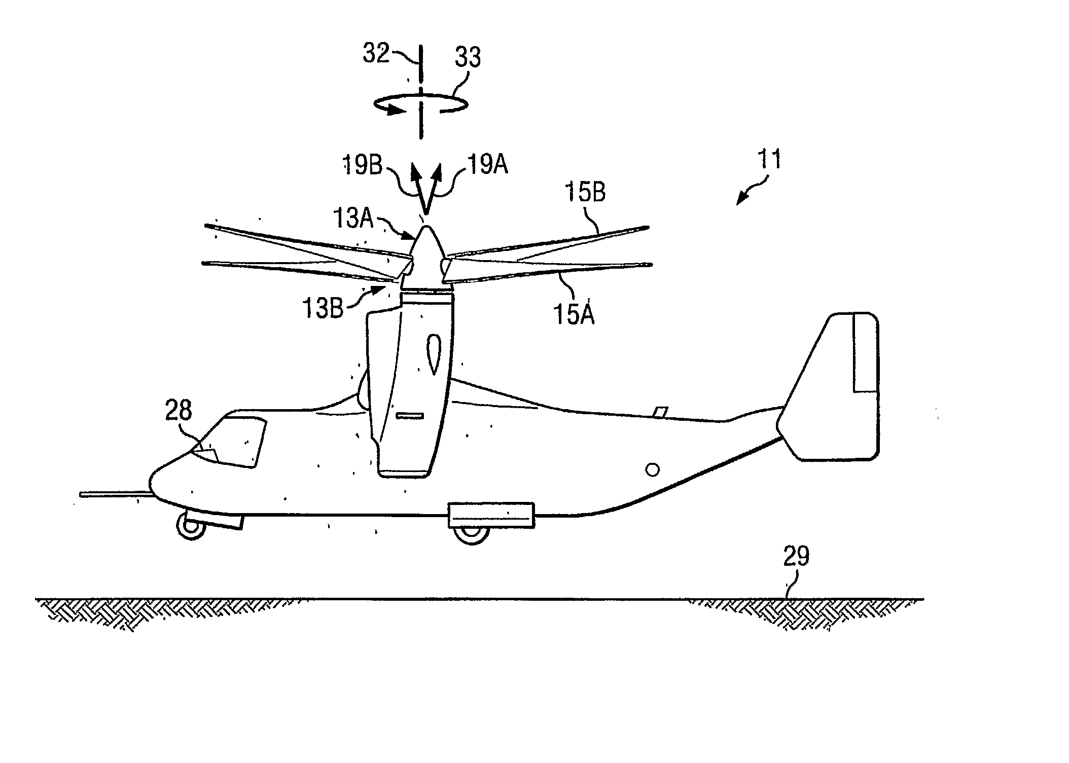
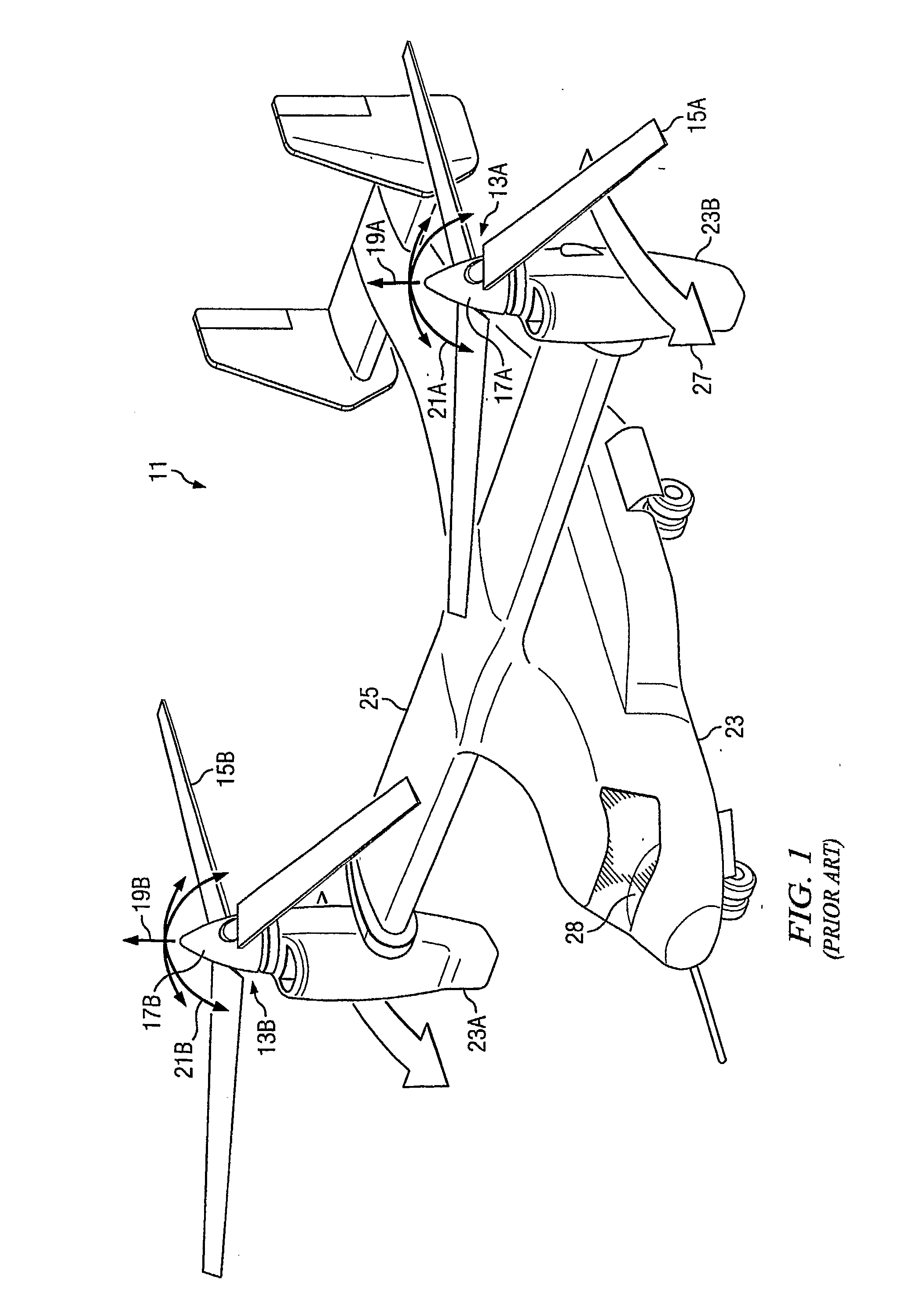
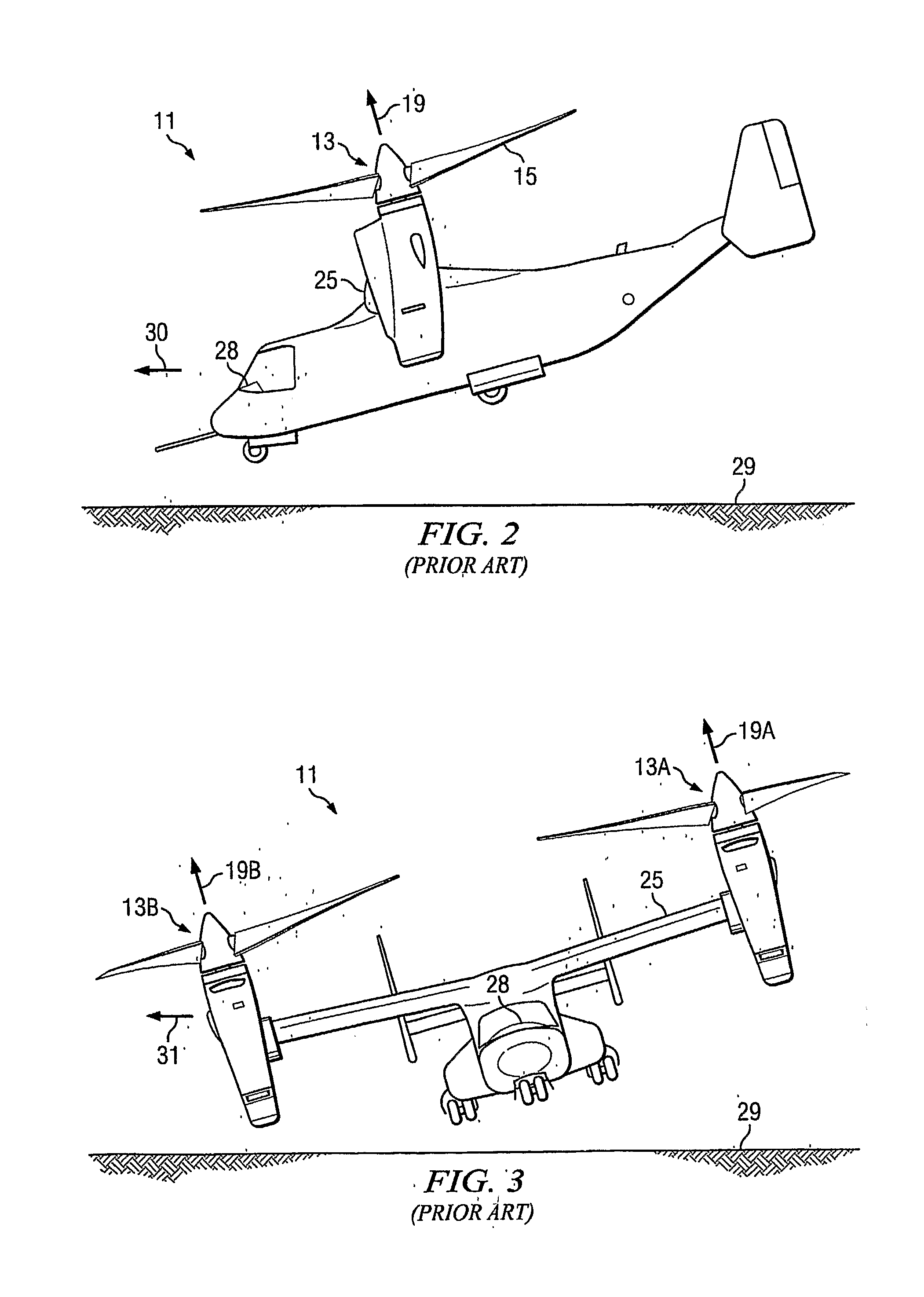
[0034] Referring now to FIG. 5, a tiltrotor aircraft 34 is depicted in a hover above ground 35. Aircraft 34 is constructed in the same manner as aircraft 11, described above, but the flight control system (FCS) 36 in aircraft 34 uses the control methods of the present invention to automatically control the flight of aircraft 34 in response to control inputs by a pilot or electronic system. Rotors 37, comprising hub 39 and multiple blades 41, are powered by engines carried within nacelles 43. Nacelles 43 are rotatably mounted to the outer ends of wings 45, and wings 45 are affixed to fuselage 47. As described above, the pitch of each blade 41 is controlled by collective and cyclic swashplate controls (not shown) located within hub 39. As described herein, a single reference number may be used to refer to both left and right components (as viewed when seated in the aircraft) when the description applies to both components. Specific reference numbers are used for clarity to refer to sp...


PUM


Abstract

A method and apparatus provide for automatically controlling the flight of a tiltrotor aircraft while the aircraft is in flight that is at least partially rotor-borne. The method and apparatus provide for automatically tilting nacelles in response to a longitudinal-velocity control signal so as to produce a longitudinal thrust-vector component for controlling longitudinal velocity of the aircraft. Simultaneously, cyclic swashplate controls are automatically actuated so as to maintain the fuselage in a desired pitch attitude. The method and apparatus also provide for automatically actuating the cyclic swashplate controls for each rotor in response to a lateral-velocity control signal so as to produce a lateral thrust-vector component for controlling lateral velocity of the aircraft. Simultaneously, collective swashplate controls for each rotor are automatically actuated so as to maintain the fuselage in a desired roll attitude. The method and apparatus provide for yaw control through differential longitudinal thrust produced by tilting the nacelles.

Description

TECHNICAL FIELD [0001] The present invention relates in general to the field of flight control of aircraft. In particular, the present invention relates to apparatus and methods for controlling the flight of a tiltrotor aircraft. DESCRIPTION OF THE PRIOR ART [0002] A rotary wing aircraft, such as a helicopter or the tiltrotor aircraft 11 shown in FIG. 1, produces lift with at least one main rotor 13, which comprises multiple wings, or blades 15, attached to a rotating hub 17. Each blade 15 has an airfoil cross-section, and lift is produced by moving blades 15 in a circular path as hub 17 rotates. As shown in the figures, the left and right sides of aircraft 11 are generally mirror images of each other, having corresponding components on each side of aircraft 11. As described herein, a single reference number may be used to refer to both left and right (as viewed if seated in the aircraft) components when the description applies to both components. Specific reference numbers are used...

Claims


Application Information

Patent Timeline
IPC IPC(8): B64C27/52
CPCB64C27/52G05D1/0858B64C29/0033
Inventor BUILTA, KENNETH E.
Owner TEXTRON INNOVATIONS
Why Eureka
Try Eureka