
Mica tape, electrical rotating machine coil, and electrical rotating machine comprising the electrical rotating machine coil

Active Publication Date: 2007-09-27
KK TOSHIBA
View PDF8 Cites 31 Cited by
  • Summary
  • Abstract
  • Description
  • Claims
  • Application Information

AI Technical Summary

Benefits of technology

[0022] According to the present invention, added to the glass cloth is an inorganic filler excellent in the thermal conductivity and having a Mohs harness not higher than that of the glass cloth to form a mica tape according to the present invention. As a result, even if the mica tape is wound about the conductive portion while applying a prescribed tension to the mica tape, the mica tape is not broken. In addition, it is possible to form an insulating layer exhibiting the highest heat conductivity owned by the inorganic filler. It should also be noted that, if an electrical rotating machine coil is formed by winding a plurality of times the mica tape of the present invention about a coil conductor, it is possible to miniaturize the electrical rotating machine coil as well as the electrical rotating machine and to improve the reliability of the electrical rotating machine, compared with the conventional electrical rotating machine.

Problems solved by technology

However, since the bonding strength among the scale-like mica foils is weak, it is difficult to use a tape prepared by simply bonding the mica foils for the fastening purpose.
In the case of using a mica tape prepared by adding aluminum oxide having a Mohs hardness of 12 as a filler, it was possible for the aluminum oxide to damage the glass cloth 64 particularly at the corner portion of the conductor when the mica tape is wound about the conductive wire having a rectangular cross section, with the result that the glass cloth 64 is broken, leading possibly to the breakage of the mica tape.
It follows that the mica tape tends to be broken easily so as to make it impossible to increase the tension as much as required.
Such being the situation, the heat dissipation and the insulating properties were not sufficiently satisfactory.

Method used


Image

  • Mica tape, electrical rotating machine coil, and electrical rotating machine comprising the electrical rotating machine coil
  • Mica tape, electrical rotating machine coil, and electrical rotating machine comprising the electrical rotating machine coil
  • Mica tape, electrical rotating machine coil, and electrical rotating machine comprising the electrical rotating machine coil

Examples


first embodiment

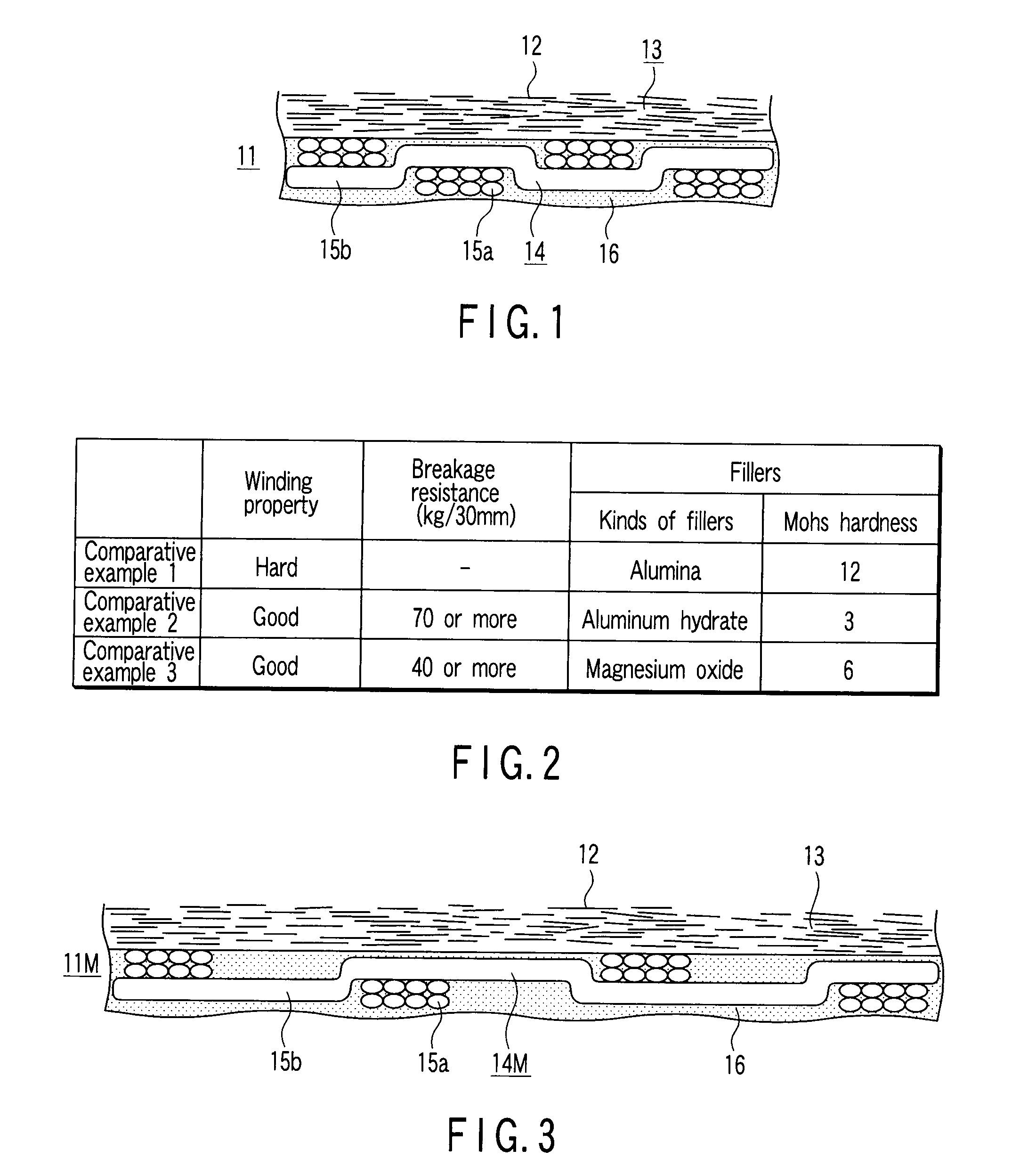
[0032]FIG. 1 is a cross-sectional view showing the construction of a mica tape according to a first embodiment of the present invention.

[0033] The mica tape 11 shown in FIG. 1 comprises a mica layer 13 including scale-like mica foils 12 arranged to form the layer, a glass cloth 14 laminated on the lower side of the mica layer 13, and an inorganic particle layer 16 added to the glass cloth 14.

[0034] The glass cloth 14 is prepared by weaving warps 15a and wefts 15b each obtained by stranding a plurality of glass fibers. These warps 15a and wefts 15b are woven at a prescribed density. In the embodiment shown in the drawing, 8 warps 15a and 8 wefts 15b are arranged in the vertical and lateral directions so as to weave the glass cloth 14. A quartz glass having a Mohs hardness of 7 is used as a glass material used for forming the glass fiber.

[0035] An electrically insulating glass cloth is used as the glass cloth 14. The density, the tensile strength, etc. of the glass cloth are define...

second embodiment

[0046] A second embodiment of the present invention will now be described.

[0047] The mica tape according to the second embodiment is substantially equal to that according to the first embodiment described above, except that a binder insoluble in an impregnating resin used in the heating step of the coil under pressure is used for holding an inorganic filler 9.

[0048] A mica tape was wound a plurality of times about a modeling coil conductor made of an aluminum bar having a rectangular cross section by applying a prescribed tension to the mica tape, followed by performing a vacuum drawing for 2 hours or more to subsequently allow the mica tape to be impregnated with an impregnating thermosetting resin.

[0049] The impregnating resin noted above comprised 45% by weight of alicyclic epoxy compound, 40% by weight of an acid anhydride curing agent and 15% by weight of a reactive diluent, which was disclosed in Japanese Patent Disclosure (Kokai) No. 11-345733.

[0050] Since the impregnatin...

third embodiment

[0052] A third embodiment of the present invention will now be described.

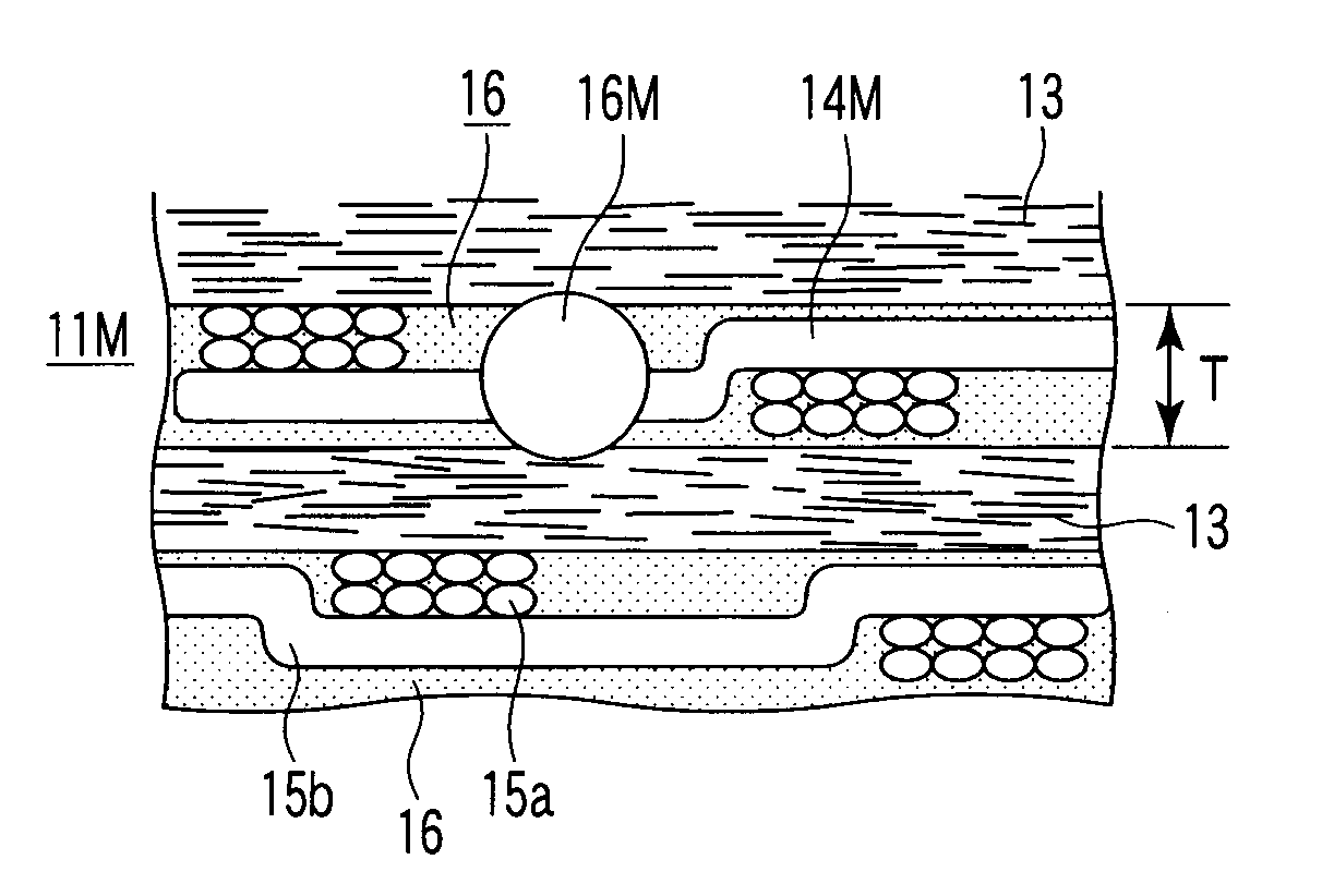
[0053] In the third embodiment, a sparse glass cloth having a wide clearance among the adjacent yarns is used as a glass cloth constituting one element of the mica tape. As shown in, for example, FIG. 3, the density of the warps 15a of the glass cloth 14M was made half the density of the warps 15a shown in FIG. 1. In this case, the density of the wefts 15b was made equal to that shown in FIG. 1. In this case, the density of the warps 15a of the glass cloth 14M is made lower, with the result that a large number of inorganic fillers 16 are arranged in the mesh defined by the warps 15a and the wefts 15b of the glass cloth 14. It follows that the contact area among the warp 15a and the weft 15b of the glass fiber and the inorganic filler 16 is made larger than that in the case of FIG. 1.

[0054] In the case of using inorganic filler particles having a Mohs hardness exceeding 7 such as alumina as in the conventional...


PUM

PropertyMeasurementUnit
Fractionaaaaaaaaaa
Fractionaaaaaaaaaa
Thicknessaaaaaaaaaa

Abstract

A mica tape comprising a mica foil, a glass cloth, and an inorganic filler arranged on the glass cloth, wherein the mica tape is wound a plurality of times about an outer circumferential surface of a conductor portion of an electrical rotating machine coil so as to form an insulating layer for the coil, and the inorganic filler has a Mohs hardness falling within a range of 1 to 7 and exhibits a heat conductivity superior to those of the mica foil and the glass cloth, whereby, the inorganic filler is excellent in the heat conductivity and has a Mohs hardness not lower than that of the glass cloth contained in the mica tape, when used together with the inorganic filler.

Description

CROSS REFERENCE TO RELATED APPLICATIONS [0001] This is a Continuation Application of PCT Application No. PCT / JP2006 / 319365, filed Sep. 28, 2006, which was published under PCT Article 21(2) in Japanese. [0002] This application is based upon and claims the benefit of priority from prior Japanese Patent Application No. 2005-283422, filed Sep. 29, 2005, the entire contents of which are incorporated herein by reference.BACKGROUND OF THE INVENTION [0003] 1. Field of the Invention [0004] The present invention relates to a mica tape that is wound a plurality of times around the outer circumferential surface of a conductor of an electrical rotating machine coil so as to form an electric insulating layer, to an electrical rotating machine coil prepared by winding the mica tape around the electrical conductor so as to form a good insulating layer having a good heat conductivity, and to an electrical rotating machine using the electrical rotating machine coil. [0005] 2. Description of the Relat...

Claims


Application Information

Patent Timeline
IPC IPC(8): H02K15/12H01B7/00H02K3/00
CPCH01B3/04H01F27/323Y10T428/294H02K3/40H02K3/30Y10T428/31525Y10T442/3252
Inventor SAWA, FUMIOIWATA, NORIYUKIHATANO, HIROSHIOKAMOTO, TETSUSHIMUKAI, KAZUMAASO, TOSHIYUKIKAWAHARA, MAKOTOKAKIUCHI, MIKIO
Owner KK TOSHIBA
Learn More