Eureka AIR delivers breakthrough ideas for toughest innovation challenges, trusted by R&D personnel around the world.

Video signal processing

Inactive Publication Date: 2007-09-27
SEIKO EPSON CORP
View PDF4 Cites 15 Cited by
  • Summary
  • Abstract
  • Description
  • Claims
  • Application Information

AI Technical Summary

Benefits of technology

[0008]An object of the present invention is to provide a technology that enables black-white expansion with no color change, while attaining reduction of the overall circuit scale.
[0015]All the three color-defining parameters, that is, the luminance signal, the first color difference signal, and the second color difference signal, are expanded based on the luminance ratio n (=Y′ / Y). The white-black expansion thus does not lead to a color change. The video signal processing device of the first aspect of the invention requires only one module for attaining the black-white expansion of the luminance signal and simple circuit structures (for example, multiplication circuits) for expanding the first color signal and the second color signal. The video signal processing device thus enables black-white expansion with no color change, while attaining reduction of the overall circuit scale.
[0017]This arrangement ensures external output of the expanded luminance signal, the expanded first color difference signal, and the expanded second color difference signal at the identical timing, thus effectively preventing misalignment of a displayed video image.
[0020]The computer program product of the second aspect of the invention enables the black-white expansion with no color change, like the video signal processing device of the invention described above. The computer program product attains the one-step black-white expansion of the luminance signal and requires only the simple arithmetic operations with regard to the first color difference signal and the second color difference signal, thus desirably reducing the required throughput of the computer used for execution of the computer program.
[0022]The video signal processing method of the third aspect of the invention enables the black-white expansion with no color change, like the video signal processing device and the computer program of the invention described above. The video signal processing method attains the one-step black-white expansion of the luminance signal and requires only the simple arithmetic operations with regard to the first color difference signal and the second color difference signal, thus desirably simplifying the overall processing flow.

Problems solved by technology

The black-white expansion of the luminance signal, however, undesirably changes the color of the video signal.
This proposed technique requires three expansion circuits for the R, G, and B signals and undesirably expands the circuit scale.

Method used


Image

  • Video signal processing
  • Video signal processing
  • Video signal processing

Examples


first embodiment

A. First Embodiment

A1. General Configuration of Liquid Crystal Projector

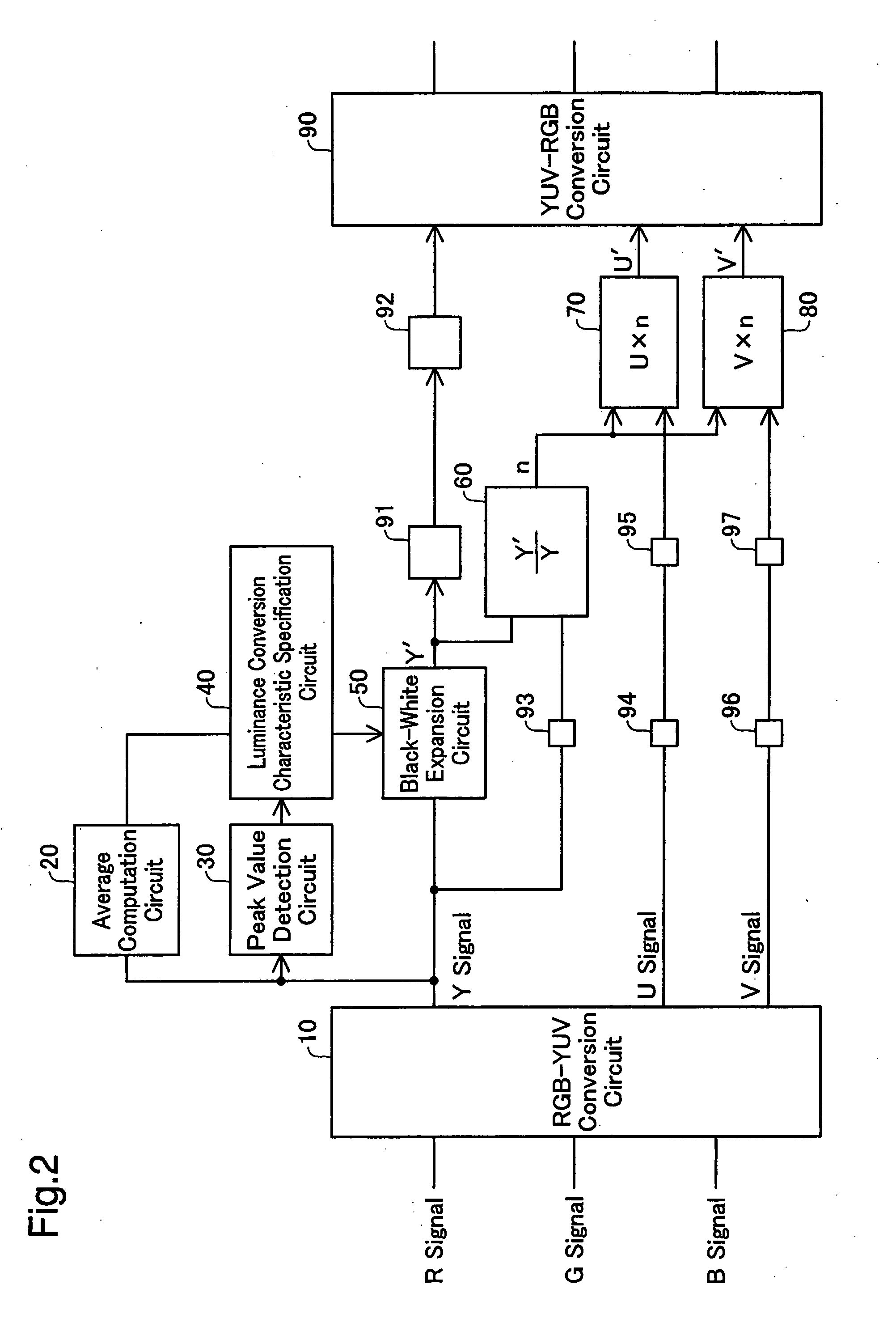
A2. Video Signal Processing Circuit

A3. Functions and Effects

B. Second Embodiment

C. Modifications

A. First Embodiment

A1. General Configuration of Liquid Crystal Projector

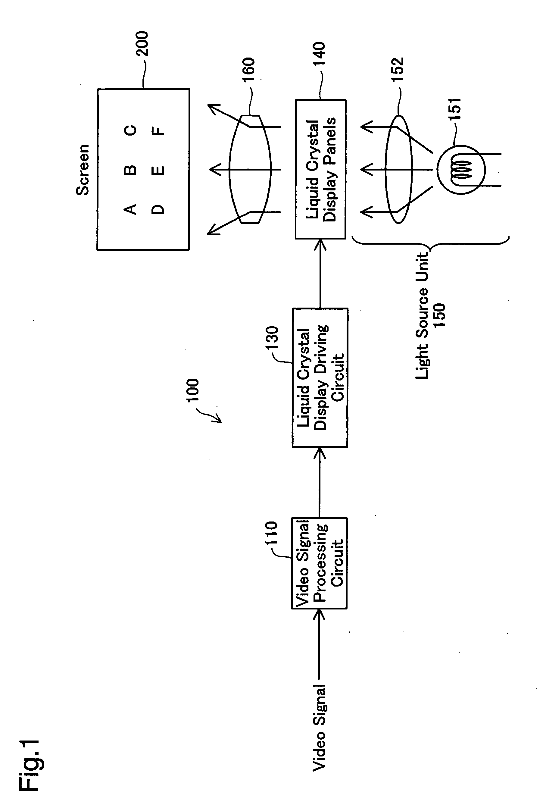
[0029]FIG. 1 is a block diagram showing the general configuration of a liquid crystal projector 100 as one application of video signal processing device in a first embodiment of the invention. The liquid crystal projector 100 includes a video signal processing circuit 110, a liquid crystal display driving circuit 130, liquid crystal display panels 140, a light source unit 150, and a projection lens 160 and displays video signals input into the video signal processing circuit 110 on a screen 200. The video signals may be input in real time from input devices (not shown), such as cameras, scanners, and personal computers, into the video signal processing circuit 110 or may be read on the video signal processing circuit 110 from computer readable sto...

second embodiment

B. Second Embodiment

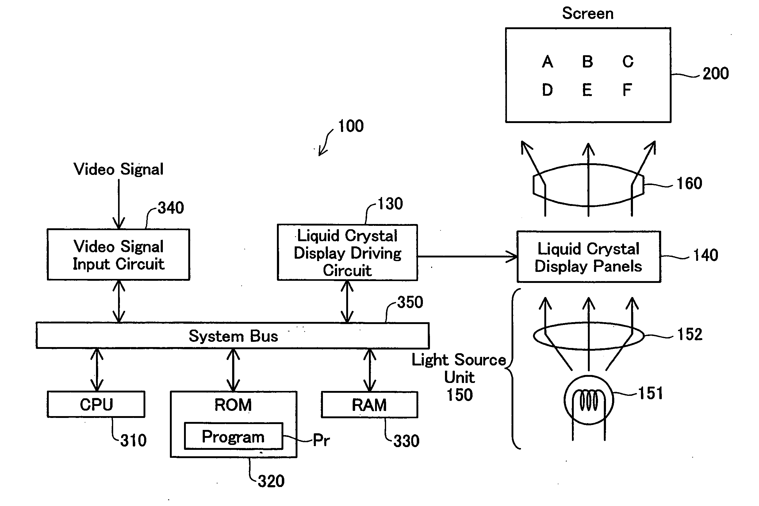
[0052]FIG. 4 is a block diagram showing the general configuration of another liquid crystal projector 300 as another application of video signal processing device in a second embodiment of the invention. The liquid crystal projector 300 of the third embodiment has the liquid crystal display driving circuit 130, the liquid crystal display panels 140, the light source unit 150, and the projection lens 160, which are identical with those included in the liquid crystal projector 100 of the first embodiment. The primary difference from the first embodiment is a computer system included in the liquid crystal projector 300 of the second embodiment as the application of the video signal processing device, in place of the video signal processing circuit 110 of the first embodiment. The computer system includes a CPU 310, a ROM 320, a RAM 330, a video signal input circuit 340, and a system bus 350 that mutually connects the respective elements 310 through 340. The liquid c...

modification 2

(2) Modification 2

[0062]The video signal processing device of the first embodiment has the first multiplication circuit 70 and the second multiplication circuit 80, which are respectively equivalent to the ‘first color difference signal expansion module’ and the ‘second color difference signal expansion module’ of the invention. These multiplication circuits are not essential but may be replaced by operation circuits for computing values approximate to the multiplication results. The multiplications or the operations for computing the approximate values to the multiplication results are not restrictive, but any other suitable structure may be adopted to expand the first color difference signal U and the second color difference signal V based on the luminance ratio ‘n’. Application of the technique of the invention effectively prevents a color change accompanied by expansion of only the luminance signal Y in any structure. Like this modification of the first embodiment, the operation...


PUM


Abstract

In a video signal processing device, a black-white expansion circuit performs black-white expansion of a luminance signal (Y signal) included in a video signal to generate an expanded luminance signal (Y′ signal). A luminance ratio ‘n’ is computed as the rate of the expanded luminance signal (Y′ signal) to the luminance signal (Y signal). A first color difference signal (U signal) and a second color difference signal (V signal) included in the video signal are respectively multiplied by the luminance ratio ‘n’ (=Y′ / Y) to give an expanded first color difference signal (U′ signal) and an expanded second color difference signal (V′ signal). This arrangement of the invention effectively enables black-white expansion with no color change, while attaining reduction of the overall circuit scale.

Description

CROSS REFERENCE TO RELATED APPLICATIONS[0001]The present application claims the priority based on Japanese Patent Application No. 2006-83004 filed on Mar. 24, 2006, the disclosure of which is hereby incorporated by reference in its entirety.BACKGROUND OF THE INVENTION[0002]1. Field of the Invention[0003]The present invention relates to a video signal processing technique and more specifically pertains to a technique of black-white expansion.[0004]2. Description of the Related Art[0005]In the process of image display by a liquid crystal projector, when a black-most portion of an input video signal is higher than a predetermined level, the black-most portion expanded to the predetermined level in the direction of black. When a white-most portion of an input video signal is lower than a predetermined level, the white-most expanded to the predetermined level in the direction of white.[0006]The object of such black-white expansion is generally a luminance signal. The black-white expansio...

Claims


Application Information

Patent Timeline
IPC IPC(8): G09G3/36
CPCG09G3/36G09G2360/16G09G2320/0626G09G5/02
Inventor KOYAMA, FUMIOYAGI, YASUO
Owner SEIKO EPSON CORP
Why Eureka
Eureka Blog
Learn More